Building displacement turning method

A technology for building and rear displacement, which is applied in the direction of building construction, construction, building maintenance, etc. It can solve the problems that affect the displacement, the bottom of the underpinning beam is uneven, cracking, etc., so as to avoid additional internal force and facilitate the displacement. Bit, the effect of high flatness

Active Publication Date: 2012-10-10
SHANDONG JIANZHU UNIV
View PDF8 Cites 16 Cited by
  • Summary
  • Abstract
  • Description
  • Claims
  • Application Information

AI Technical Summary

Problems solved by technology

However, if the underpinning beam after the steering is cast at the same time as the underpinning beam before the steering, there will be the following two problems: (1) The bottom formwork of the underpinning beam after the steering cannot be supported on the steel roller
The top support of the bottom formwork of the underpinning beam after turning will be directly supported on the foundation soil. If the foundation deformation is large, the bottom of the underpinning beam after

Method used


Image

  • Building displacement turning method
  • Building displacement turning method
  • Building displacement turning method

Examples


specific Embodiment approach

[0021] The present invention will be further described below in conjunction with the accompanying drawings and embodiments.

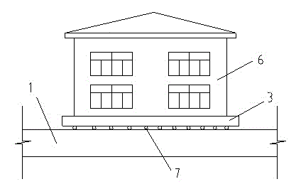
[0022] Such as Figure 1-Figure 4 Shown, a kind of building displacement steering method, the steps are as follows:

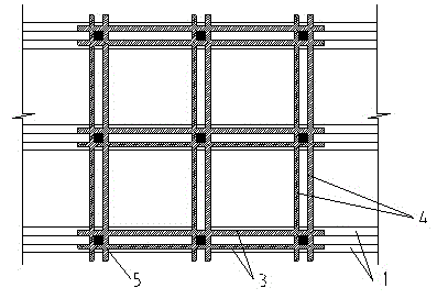
[0023] 1) For the building 6 that needs to be turned, only the roller 7 under the underpinning beam before turning is laid before shifting, and the shifting track 1 before turning, the shifting track 2 after turning and the underpinning beam 3 before turning are poured;

[0024] 2) Cut off the column or wall 5 from the foundation, and move to the turning position by traction or pushing equipment;

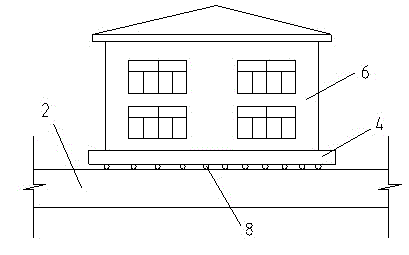
[0025] 3) Lay the roller shaft 8 under the steering rear underpinning beam on the shifting track 2 after steering, and support the channel steel on the roller shaft 8 under the steering rear underpinning beam as the bottom template pouring to make the steering rear underpinning beam 4;

[0026] 4) Cut the channel steel near the roller 7 unde...


PUM


Abstract

The invention discloses a building displacement turning method. The building displacement turning method comprises the following steps: (1) pouring and manufacturing a turning front displacement railway, a turning rear displacement railway and a turning front support exchanging beam before the displacement on a building which needs to turn; (2) cutting off a column or a wall from a foundation so as to transfer to the turning position through a traction or pushing gear; (3) paving steel rolling shafts on the turning rear displacement railway, and supporting a channel steel on a steel rolling shaft to be used as a bottom template to pour and manufacture the turning rear support exchanging beam; (4) cutting the channel steel adjacent to the rolling shaft arranged below the turning front support exchanging beam, taking out the rolling shafts, changing the transmission pipeline of the building load from the displacement front support exchanging beam, the displacement front rolling shafts and the displacement front railway to the displacement rear support exchanging beam, the displacement rear rolling shafts and the displacement rear railway; and (5) installing the traction or pushing gear after displacement, and continuing with the displacement. The building displacement turning method provided by the invention does not need a lifting jack to jack to complete the rolling shafts turning, thereby avoiding additional internal force generated by jack deformation; the rolling shafts are paved on a turning rear railway so as to manufacture a turning rear support exchanging beam, the beam bottom deformation is small, the flatness is high, and the building displacement turning method is beneficial for displacement.

Description

[0001] technical field [0002] The invention relates to the technical field of civil engineering, in particular to a method for shifting and steering a building. Background technique [0003] At present, during the process of building relocation, sometimes the predetermined location cannot be reached at one time, and it needs to be turned in the middle to be successfully in place. If the weight of the building is relatively light, the sliding block is used as the walking device, and only the direction of the traction device needs to be changed, and the steering can be completed smoothly without handling the sliding block. And adopt roller or tackle as walking device, because roller or tackle can only move to single direction, turn to problem and just become complicated. [0004] For the usual building shifting, shifting tracks are built on both sides of the column (wall), steel rollers are laid on the shifting rails, channel steel is supported on the steel rollers as a bot...

Claims


Application Information

Patent Timeline
IPC IPC(8): E04G23/06
Inventor 贾强张鑫
Owner SHANDONG JIANZHU UNIV
Why Eureka
Try Eureka