
Cylinder cover oil-gas separation device

A separation device, oil and gas technology, applied in the direction of machines/engines, crankcase ventilation, mechanical equipment, etc., can solve the problems of low oil and gas separation efficiency, low life, high cost, etc., to achieve good oil and gas separation effect, long service life, structure simple effect

Inactive Publication Date: 2012-10-10
NINGBO YINZHOU DLT TECH CO LTD
View PDF6 Cites 0 Cited by
  • Summary
  • Abstract
  • Description
  • Claims
  • Application Information

AI Technical Summary

Problems solved by technology

[0002] With the increasingly stringent emission requirements of automobile engines, the current crankcase ventilation system must be a closed cycle. Blow-by gas and engine oil oil and gas must be circulated to the engine intake system and burned in the cylinder. This has a great impact on the oil-gas separation efficiency. High requirements, try to separate the oil droplets, otherwise the engine will burn oil, which will affect the emission performance and the reliability of the engine
[0003] In the prior art, two structures are mainly used for gas-oil separation. One is a baffle-type oil-gas separation structure, which allows oil and gas to pass through the labyrinthine channels in the engine cylinder head to achieve the purpose of separating oil and gas. This structure is not efficient in oil-gas separation. The other is to add a first-stage filter element structure separator to the baffle type oil-gas separation structure. Although the separation efficiency is high, the filter element needs to be replaced regularly, so the service life is low, and the cost is high and the structure is complicated.

Method used


Image

  • Cylinder cover oil-gas separation device
  • Cylinder cover oil-gas separation device

Examples


Embodiment Construction

[0012] The present invention will be further described below in conjunction with the accompanying drawings and specific embodiments, but the present invention is not limited to the following specific embodiments.

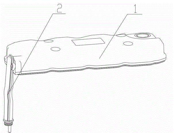
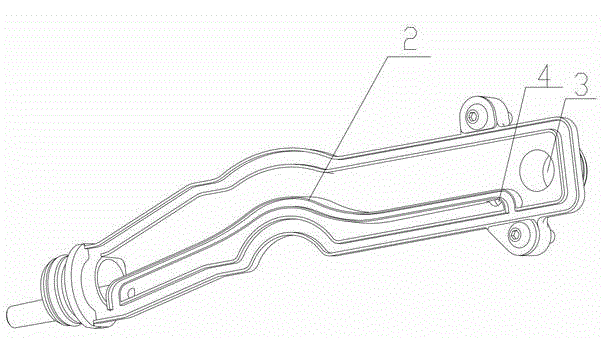
[0013] like figure 1 , figure 2 Shown: a cylinder head oil-gas separation device, including a baffle-type oil-gas separation device arranged in the cylinder head 1, it is also provided with a pipeline-type oil-gas separation device arranged outside the cylinder head 1, the pipeline-type oil-gas separation device The device is a pipeline 2 with a bend inside, and the pipeline 2 also communicates with the baffle type oil-gas separation device. The baffle plate type oil-gas separation device is well known in the prior art. The main structure is that a labyrinth composed of baffle plates is arranged in the cylinder cover 1. When the oil and gas pass through this labyrinth, the oil and gas will be separated due to the centrifugal effect and inertial effect of the oil a...


PUM


Abstract

The invention relates to the field of automobile engines, and in particular relates to a cylinder cover oil-gas separation device. The cylinder cover oil-gas separation device comprises a baffle type oil-gas separation device which is arranged in a cylinder cover (1) and is characterized by comprising a pipeline type oil-gas separation device arranged outside the cylinder cover (1), the pipeline type oil-gas separation device is a pipeline (2) provided with a bend inside, and the pipeline (2) is also communicated with the baffle type oil-gas separation device. The oil-gas separation device disclosed by the invention has the advantages of high oil-gas separation efficiency, long service life, low cost and simple structure.

Description

technical field [0001] The invention relates to the field of automobile engines, in particular to a cylinder head oil-gas separation device. Background technique [0002] With the increasingly stringent emission requirements of automobile engines, the current crankcase ventilation system must be a closed cycle. Blow-by gas and engine oil oil and gas must be circulated to the engine intake system and burned in the cylinder. This has a great impact on the oil-gas separation efficiency. High requirements, try to separate the oil droplets, otherwise the engine will burn oil, which will affect the emission performance and the reliability of the engine. [0003] In the prior art, two structures are mainly used for gas-oil separation. One is a baffle-type oil-gas separation structure, which allows oil and gas to pass through the labyrinthine channels in the engine cylinder head to achieve the purpose of separating oil and gas. This structure is not efficient in oil-gas separation....

Claims


Application Information

Patent Timeline
IPC IPC(8): F01M13/04
Inventor 胡景彦洪进
Owner NINGBO YINZHOU DLT TECH CO LTD
Learn More