Backlight module and liquid crystal display device

A technology for a liquid crystal display device and a backlight module, which is applied to lighting devices, fixed lighting devices, components of lighting devices, etc., can solve the problem of light leakage on the light-incident side of the light guide plate 40, easy to turn outwards, and increase the manufacturing cost of liquid crystal display devices. and operating energy consumption, to achieve the effect of reducing manufacturing cost and operating power consumption, improving optical coupling efficiency, and improving optical coupling efficiency.

Inactive Publication Date: 2012-10-10
TCL CHINA STAR OPTOELECTRONICS TECH CO LTD
View PDF5 Cites 15 Cited by
  • Summary
  • Abstract
  • Description
  • Claims
  • Application Information

AI Technical Summary

Problems solved by technology

[0003] With the development of technology, the light guide plate 40 used in the backlight module is made thinner and thinner. The thinner the light guide plate 40 is, the more difficult it is to align with the light source 30. At this time, the light guide plate in the above-mentioned backlight module The technical solution of aligning 40 with the light source 30 will produce the following defects: one end of the plastic frame 10 pressed against the optical film 20 is easy to turn outward (the end of the plastic frame 10 fastened to the outside of the back plate 70 is used as the axis, and the plastic frame 10 is pressed against the optical film 20). One end of the film 20 moves away from the optical film 20), so the light guide plate 40 will be misaligned with the light source 30, and the misalignment between the light guide plate 40 and the light source 30 will easily cause light leakage from the light incident side of the light guide plate 40, seriously affecting the backlight module. The light coupling efficiency and the display quality of the light-incident side of the liquid crystal display device
[0004] At the same time, due to light leakage from the light incident side of the light guide plate 40, in order to meet the requirements of the liquid crystal display device on the brightness of the backlight, the backlight module needs to use more LED lamps (light sources 30) to generate the backlight, which will increase the manufacturing cost of the liquid crystal display device. and operating energy consumption

Method used


Image

  • Backlight module and liquid crystal display device
  • Backlight module and liquid crystal display device
  • Backlight module and liquid crystal display device

Examples


Embodiment Construction

[0025] The following descriptions of the various embodiments refer to the accompanying drawings to illustrate specific embodiments in which the present invention can be practiced.

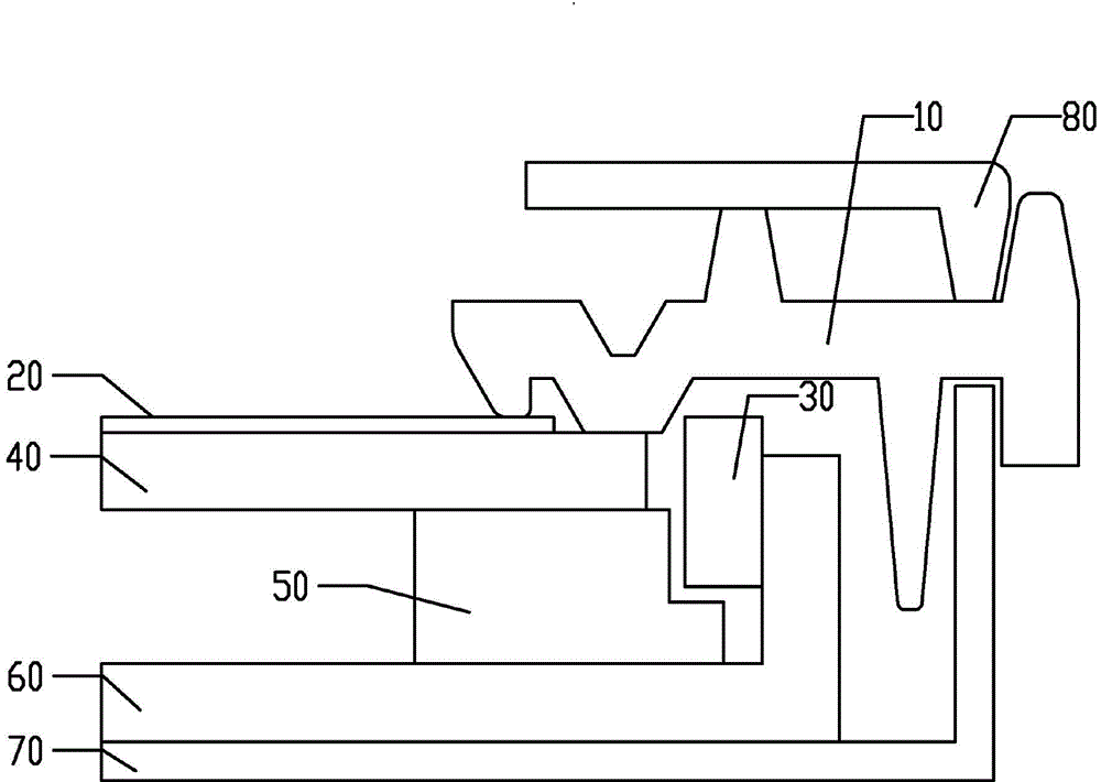
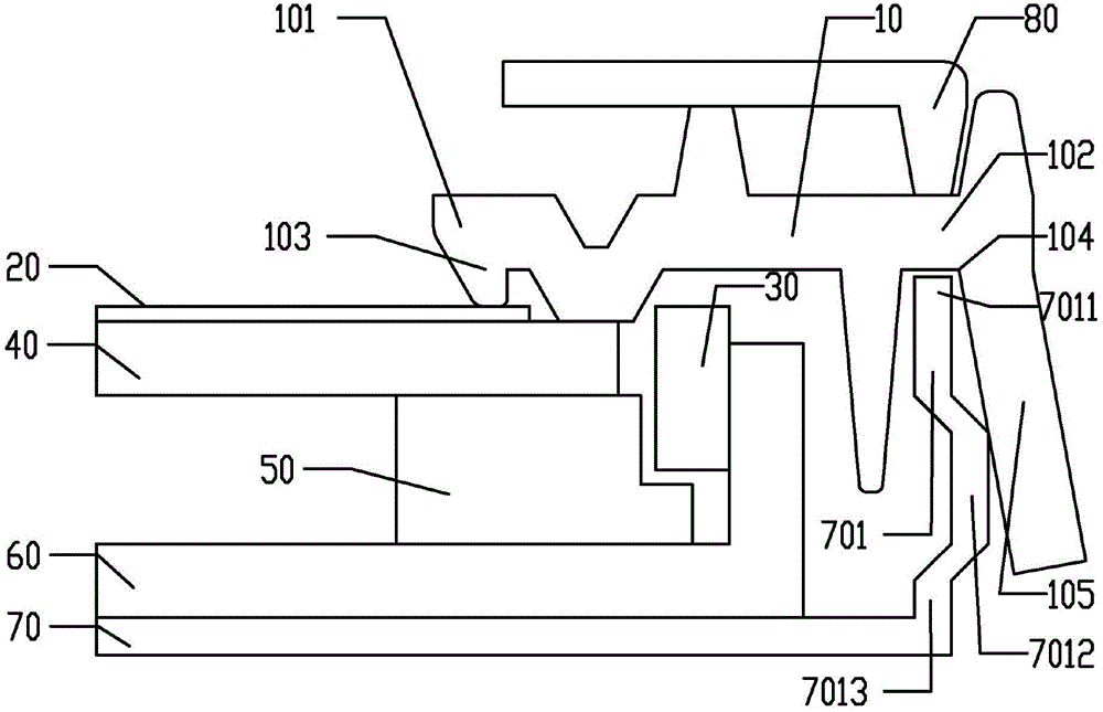
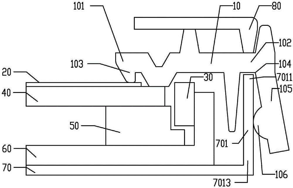
[0026] refer to figure 2 , figure 2 It is a partial schematic diagram of the first embodiment of the backlight module of the present invention. In this embodiment, the backlight module of the present invention includes a backplane 70 , a heat sink 60 , a support member 50 , a light guide plate 40 , a light source 30 , an optical film 20 , a plastic frame 10 and a frame 80 . The edge of the back plate 70 has a side wall 701, the light guide plate 40 is placed on the back plate 70, the light source 30 is placed on the side of the light guide plate 40, the optical film 20 is placed on the light guide plate 40, and the plastic frame 10 is placed on the The optical film 20 and the sidewall 701 of the backplane 70 . The plastic frame 10 has a first end 101 and a second end 102, the first end 101 is ...


PUM


Abstract

The invention discloses a backlight module which comprises a back plate, a light guide plate, a light source, an optical membrane and a rubber frame. The edge of the back plate is provided with a side wall, the light guide plate is placed on the back plate, the light source is placed on the side edge of the light guide plate, the optical membrane is arranged on the light guide plate, the rubber frame is provided with a first tail end and a second tail end, the first tail end is provided with a pressing portion, the second tail end is provided with a bending portion, the pressing portion contacts with the optical membrane, the bending portion is provided with an extension portion in a first direction, and the extension portion contacts with the side wall of the back plate. The invention further discloses a liquid crystal display device.

Description

【Technical field】 [0001] The invention relates to the technical field of liquid crystal display, in particular to a backlight module and a liquid crystal display device. 【Background technique】 [0002] In the backlight module of a traditional liquid crystal display device, such as figure 1 As shown, the light source 30 is placed on the heat sink 60 and placed on one side of the light guide plate 40, the back plate 70, the heat sink 60, the support member 50, the light guide plate 40, and the optical film 20 are stacked in order from bottom to top. Together, the backlight module of a traditional liquid crystal display device aligns the light guide plate 40 with the light source 30 in the following manner: one end of the plastic frame 10 presses the optical film 20 on the light guide plate 40, and the other end snaps together between the backplane 70 and the frame 80 of the backlight module. [0003] With the development of technology, the light guide plate 40 used in the ba...

Claims


Application Information

Patent Timeline
Patent Type & Authority Applications(China)
IPC IPC(8): F21S8/00F21V17/00G02F1/13357
CPCF21V17/00F21S8/00G02F2001/133317G02B6/0001G02B6/0088G02B6/0091G02F1/133317
Inventor 张彦学萧宇均
Owner TCL CHINA STAR OPTOELECTRONICS TECH CO LTD
Why Eureka
Try Eureka