Polaroid splicing method

A technology of polarizers and side parts, which is applied in the field of liquid crystal display manufacturing. It can solve the problems of liquid crystal display light leakage, limited splicing accuracy, and pixels that cannot be displayed normally, and achieve the effects of narrowing the interval, improving light leakage, and improving splicing yield.

Active Publication Date: 2014-06-25
TCL CHINA STAR OPTOELECTRONICS TECH CO LTD
View PDF4 Cites 0 Cited by
  • Summary
  • Abstract
  • Description
  • Claims
  • Application Information

AI Technical Summary

Problems solved by technology

However, the splicing accuracy of the existing polarizer splicing technology is limited (about 0.3 millimeters), and there will be a certain interval 800 between the two spliced ​​polarizers 80, 81, which will cause the liquid crystal display at this interval 800. Light leakage occurs, so that the pixels at the position corresponding to this interval of 800 cannot be displayed normally

Method used


Image

  • Polaroid splicing method
  • Polaroid splicing method
  • Polaroid splicing method

Examples


Embodiment Construction

[0025] In order to make the above objects, features and advantages of the present invention more comprehensible, preferred embodiments of the present invention are exemplified below and described in detail in conjunction with the accompanying drawings. Furthermore, the directional terms mentioned in the present invention, such as "up", "down", "front", "back", "left", "right", "inside", "outside", "side", etc., It is only for orientation with reference to the attached drawings. Therefore, the directional terms used are used to illustrate and understand the present invention, but not to limit the present invention.

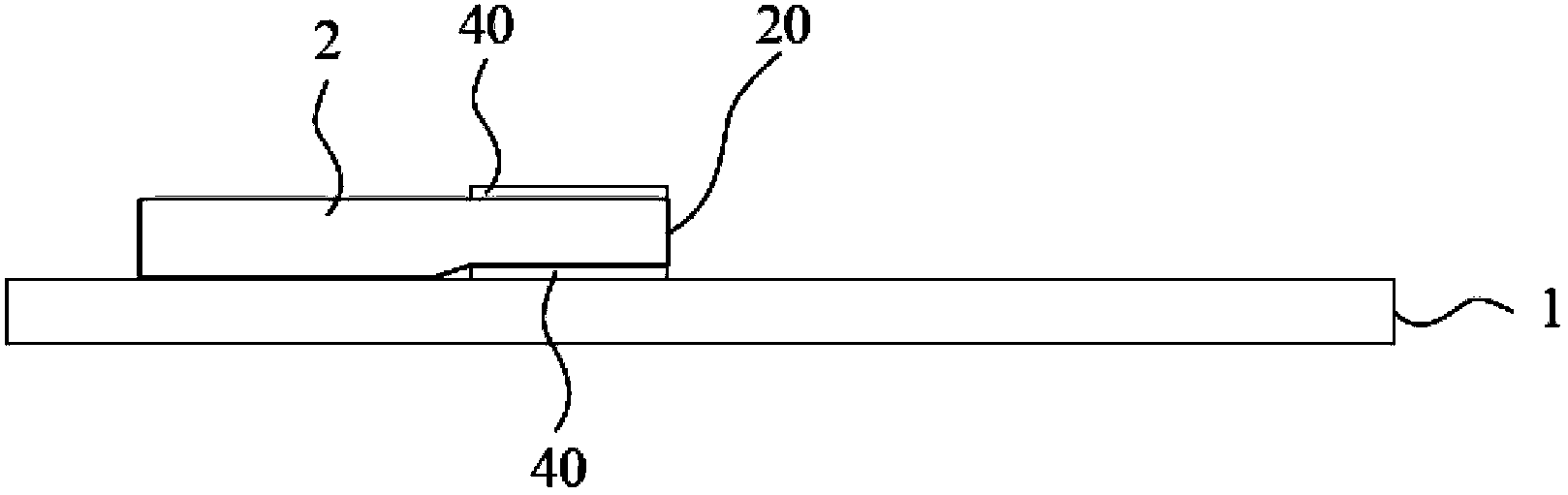
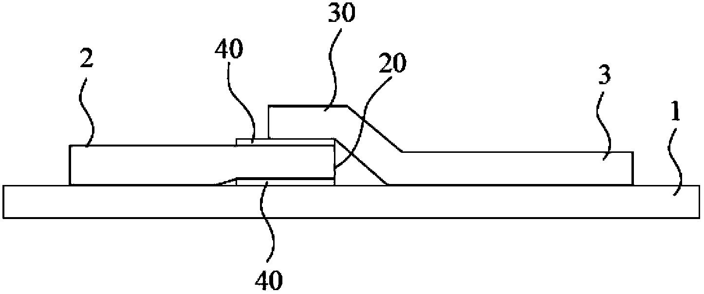
[0026] Please refer to Figure 2A~Figure 2E as shown, Figure 2A~Figure 2E It is a schematic flow chart of a preferred embodiment of the polarizer splicing method of the present invention. The polarizer splicing method of the present invention mainly comprises the following steps:

[0027] S100: providing a substrate 1;

[0028] S101: attaching a first polariz...


PUM


Abstract

A polarizer splicing method comprises the following steps: providing a substrate (1); sticking a first polarizer (2) on the substrate (1); sticking a second polarizer (3) on the substrate (1) to ensure that the side part (30) of the second polarizer (3) is correspondingly superposed with the side part (20) of the first polarizer (2); cutting the superposed part between the first polarizer (2) and the second polarizer (3) correspondingly; removing the cut parts separated from the first polarizer (2) and the second polarizer (3); and carrying out a planarizing process on the cut side parts of the first polarizer (2) and the second polarizer (3).

Description

【Technical field】 [0001] The invention relates to the manufacturing technology of liquid crystal displays, in particular to a method for splicing polarizers. 【Background technique】 [0002] Liquid crystal displays (LCDs) have been widely used in various electronic products. The current liquid crystal display mainly includes two transparent substrates, a liquid crystal layer disposed between the two substrates, and polarized films disposed on the outer surfaces of the two substrates. [0003] The aforementioned polarizer is an important part of the liquid crystal display. When the light passes through one of the polarizers, the light will become polarized light with the same polarization direction as the polarization axis of the polarizer. The liquid crystal molecules in the liquid crystal layer can be twisted under the control of an external electric field, thereby controlling whether the polarized light passes through another polarizer, so that the brightness of each pixe...

Claims


Application Information

Patent Timeline
Patent Type & Authority Patents(China)
IPC IPC(8): G02F1/1335
CPCG02B5/3025G02F1/1333G02F1/133528G02F2202/28
Inventor 贺成明程全徐亮曹荣
Owner TCL CHINA STAR OPTOELECTRONICS TECH CO LTD
Why Eureka
Try Eureka