Fuel injection valve and internal combustion engine

A technology of fuel injection valve and internal combustion engine, which is applied in the directions of low pressure fuel injection, low pressure fuel injection, fuel injection device, etc., can solve the problems of bubble breakage, uneven bubble diameter, and it is difficult to obtain uniform spray, and achieves uniform bubble diameter, The effect of uniform particle size

Inactive Publication Date: 2015-07-29
TOYOTA JIDOSHA KK
View PDF6 Cites 0 Cited by
  • Summary
  • Abstract
  • Description
  • Claims
  • Application Information

AI Technical Summary

Problems solved by technology

[0005] However, when the fuel mixed with air bubbles is injected from the injection hole, there is a concern that the bubbles will be broken due to the state around the injection hole, and the diameter of the bubbles will be uneven.
Uneven bubble diameter will make it difficult to obtain a uniform spray

Method used


Image

  • Fuel injection valve and internal combustion engine
  • Fuel injection valve and internal combustion engine
  • Fuel injection valve and internal combustion engine

Examples


Embodiment 1

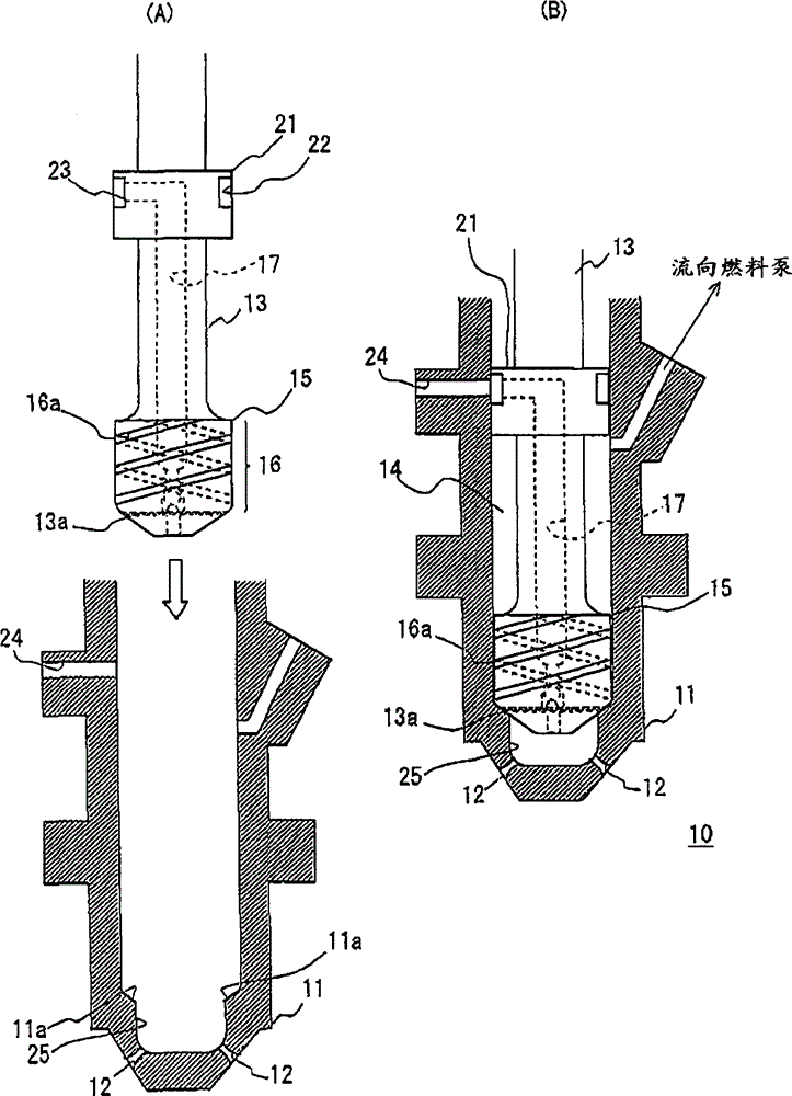
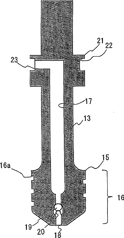
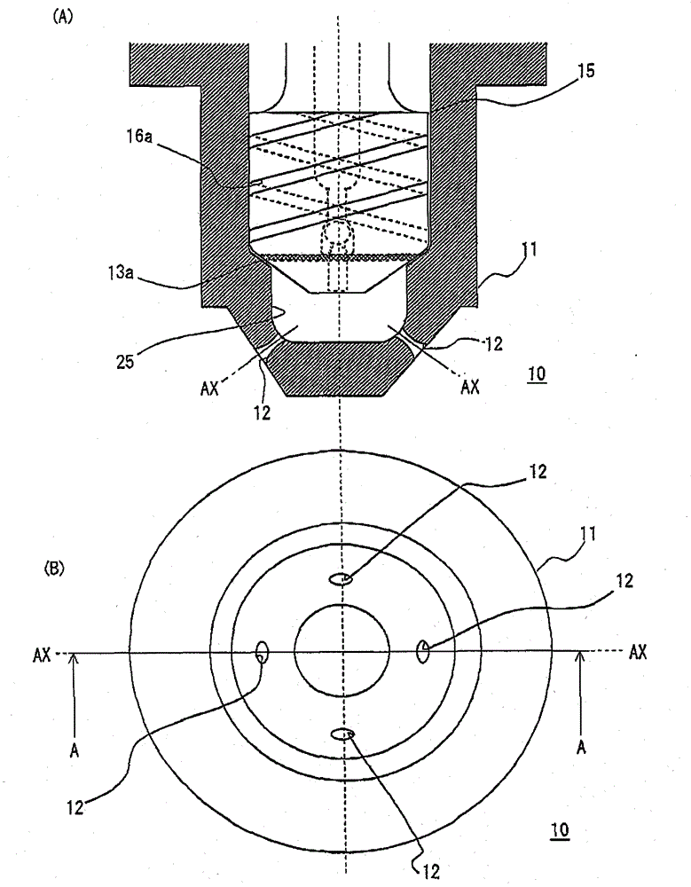
[0037] refer to figure 1 (A)~ Figure 5 (B) Embodiment 1 of the fuel injection valve disclosed in this specification will be described. figure 1 (A) is an explanatory diagram showing a state where the nozzle body 11 and the needle 13 of the fuel injection valve 10 are separated. figure 1 (B) is an explanatory diagram showing a state where the needle 13 is combined with the nozzle body 11 of the fuel injection valve 10 . figure 2 It is a sectional view of the needle 13 included in the fuel injection valve 10 . image 3 (A) is image 3 Line A-A of (B) is a cross-sectional view of the front end of the fuel injection valve as a cross-section, image 3 (B) is a front view of the fuel injection valve of the first embodiment.

[0038] The fuel injection valve 10 is mounted on an internal combustion engine, such as a gasoline engine, but the internal combustion engine is not limited to a gasoline engine, and may be any of a diesel engine using light oil as fuel, or a flexible fu...

Embodiment 2

[0063] Next, refer to Figure 6-8 Example 2 will be described. Image 6 (A) is Image 6 The B-B line of (B) is a sectional view in which the front end portion of the fuel injection valve 30 is formed as a cross section, Image 6 (B) is a front view of the fuel injection valve 30 . Figure 7 It is an explanatory diagram schematically showing the internal combustion engine 150 equipped with the fuel injection valve 30 . in addition, Figure 8 It is an explanatory diagram showing the relationship between the nozzle hole length, the spray angle, and the area ratio.

[0064] The internal combustion engine 150 includes an engine main body 151 having a combustion chamber 152 . In combustion chamber 152 , fuel injection valve 30 is mounted such that its tip is exposed in combustion chamber 152 . Fuel injection valve 30 is arranged in the center of combustion chamber 152 . In addition, the piston 153 is attached to the engine main body 151 . Furthermore, a spark plug 154 is att...

Embodiment 3

[0071] Then refer to Figure 9 , Figure 10 Example 3 will be described. Figure 9 (A) is Figure 9 The line C-C of (B) is a cross-sectional view of the front end portion of the fuel injection valve 70 . Figure 9 (B) is a front view of the fuel injection valve 70 . Figure 10 It is an explanatory diagram schematically showing an internal combustion engine 200 equipped with a fuel injection valve 70 .

[0072] The internal combustion engine 200 includes an engine main body 201 having a combustion chamber 202 . In combustion chamber 202 , fuel injection valve 70 is mounted such that its tip is exposed in combustion chamber 202 . Fuel injection valve 70 is arranged on the side of combustion chamber 202 . In addition, the piston 203 is attached to the engine main body 201 . Furthermore, a spark plug 204 is mounted so that the tip is exposed at the center of the combustion chamber 202 .

[0073] In this way, when the fuel injection valve 70 and the spark plug 204 are arran...


PUM


Abstract

A fuel injection valve includes: a nozzle body provided with an injection hole at a tip portion; a needle that is located slidably in the nozzle body and includes a seat portion seated on a seat position in the nozzle body; and an air bubble generation means generating air bubbles in a fuel flowing through the nozzle body, and when a curvature radius is R, a length of a curve is L and a constant is a, an inner peripheral shape of the injection hole includes a curving part passing through a region surrounded by a clothoid curve which is expressed by R × L = a 2 and of which the constant a is 0.95 and an clothoid curve of which the constant a is 1.05 or a region surrounded by approximate curves of the clothoid curves at a cross-section surface along a direction of axis of the injection hole.

Description

technical field [0001] The invention relates to fuel injection valves and internal combustion engines. Background technique [0002] Conventionally, there has been proposed a nozzle structure in which a mixing chamber for mixing oil and the like with pressurized air is formed inside the nozzle, and the nozzle is sprayed in a mixed state of liquid and gas (for example, Patent Document 1). [0003] [Patent Document 1] Japanese Unexamined Patent Publication No. 2009-11932 [0004] In addition, it is known that miniaturization of the spray particle size of injected fuel is effective for improvement of fuel consumption and exhaust emission of internal combustion engines. The above-mentioned Patent Document 1 is considered to promote the mixing of fuel and air and realize miniaturization of the spray particle size. [0005] However, when the fuel mixed with air bubbles is injected from the injection holes, there is a concern that the air bubbles will be broken due to the state a...

Claims


Application Information

Patent Timeline
Patent Type & Authority Patents(China)
IPC IPC(8): F02M69/00
CPCF02M67/12F02M61/163F02M57/04
Inventor 小林辰夫
Owner TOYOTA JIDOSHA KK
Why Eureka
Try Eureka