
Battery pack

A battery packaging and battery technology, applied to secondary batteries, battery temperature control, battery pack components, etc., can solve problems such as failure of heating components and failure to ensure normal operation, and achieve the effect of omitting heat dissipation components

Inactive Publication Date: 2012-10-10
SANYO ELECTRIC CO LTD
View PDF7 Cites 12 Cited by
  • Summary
  • Abstract
  • Description
  • Claims
  • Application Information

AI Technical Summary

Problems solved by technology

This is because the abnormal temperature rise of the heat-generating parts will not only lead to the failure of the element, but also cannot guarantee the normal operation.

Method used


Image

  • Battery pack
  • Battery pack
  • Battery pack

Examples


Embodiment approach 1

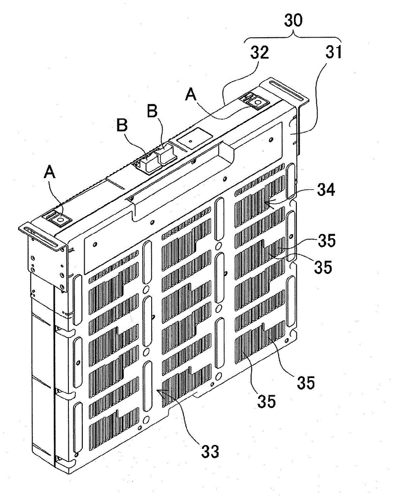
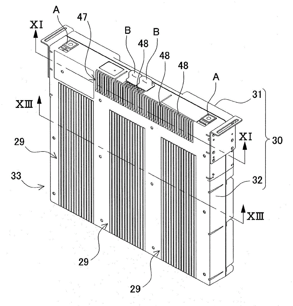
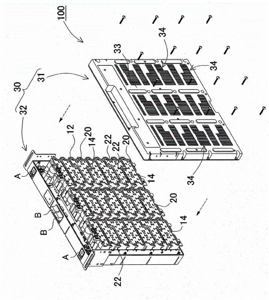
[0048] refer to Figure 1 to Figure 13 An example in which the battery pack 100 according to Embodiment 1 of the present invention is applied to a backup power supply device will be described. In the above figure, figure 1 is an external perspective view of the battery package 100 viewed from the front, figure 2 is seen from the back figure 1 A perspective view of the battery package 100, image 3 yes figure 1 An exploded perspective view of the battery package 100, Figure 4 From image 3 The front view of the battery package 100 with the first shell 31 removed, Figure 5 yes Figure 4 A longitudinal sectional view at line V-V of Figure 6 yes means image 3 An exploded perspective view of the housing member inside the battery package 100, Figure 7 is a perspective view of the battery block 10, Figure 8 yes Figure 7 An exploded perspective view of the battery block 10, Figure 9 is a perspective view showing the inner surface side of the surface plate 33, ...


PUM

PropertyMeasurementUnit
thicknessaaaaaaaaaa

Abstract

In order to simplify the assembly of a battery back while adopting a configuration which efficiently cools heat-generating parts, a battery pack is provided with a main circuit board (40) which is connected to a unit cell (11) of the battery block (10), and with a slab-shaped radiator block (42) which is fixed to the heat-generating part (41) in a heat-coupled state. An encapsulating case (30) is formed in a box shape with a greater width than thickness, and comprising two surface plates (33) facing one another and sidewalls which close-off the outer periphery of said surface plates (33). The radiator block (42) is separated on the inside of the encapsulating case (30) so as not to overlap with the battery block (10), and the radiator block (42) is positioned in the inside of the encapsulating case (30) in parallel with the surface plate (33) and in a heat-coupled state with the surface facing the surface plate (33). The heat generated by the heat-generating part (41) is absorbed by the radiator block (42) and radiated from the surface plate (33).

Description

technical field [0001] The present invention relates to a battery pack formed by accommodating a battery block and a heat-generating component in an outer case, and more particularly to a battery pack capable of efficiently dissipating heat from the heat-generating component, wherein the battery block is formed by combining a plurality of rechargeable cells. The battery is accommodated in the battery holder, and the heat generating member is connected to the battery of the battery block. Background technique [0002] The battery pack can increase the output voltage by connecting a plurality of batteries in series, or increase the output current by connecting a plurality of batteries in parallel. Since heat-generating components such as transistors such as FETs and diodes are accommodated in the battery package, it is particularly important to efficiently dissipate heat from these heat-generating components. This is because an abnormal temperature rise of the heat-generating...

Claims


Application Information

Patent Timeline
Patent Type & Authority Applications(China)
IPC IPC(8): H01M2/10H01M10/60H01M10/613H01M10/627H01M10/653H01M10/6551H01M10/6554H01M50/209H01M50/227H01M50/284
CPCY02E60/12H01M10/5046H01M10/5004H01M10/0525H01M10/5067H01M2/1077H01M10/6563H01M10/6551H01M10/613Y02E60/10H01M50/209H01M50/284H01M50/227
Inventor 宫前一朗上原雄司川畑政博
Owner SANYO ELECTRIC CO LTD
Learn More