CT (computed tomography) scanning image rebuilding method and device

A technology of image reconstruction and CT scanning, applied in image data processing, 2D image generation, computed tomography scanners, etc. The effect of directional resolution, the effect of reducing the interpolation width

Active Publication Date: 2012-10-17
NEUSOFT MEDICAL SYST CO LTD
View PDF8 Cites 21 Cited by
  • Summary
  • Abstract
  • Description
  • Claims
  • Application Information

AI Technical Summary

Problems solved by technology

[0004] In the traditional z-axis direction fly-focus reconstruction technology, it is generally used to perform fly-focus interpolation in the projection data space, that is, the data reconstruction process, and then use the obtained correction data to carry out back-projection reconstruction, which makes the interpolation in the back-projection process is Based on the interpolation results of the flying focal point, the interpolation width is actually widened, so that small objects smaller than the width cannot be resolved, and the resolution in the z-axis direction is reduced.

Method used


Image

  • CT (computed tomography) scanning image rebuilding method and device
  • CT (computed tomography) scanning image rebuilding method and device
  • CT (computed tomography) scanning image rebuilding method and device

Examples


Embodiment Construction

[0045] In order to enable those skilled in the art to better understand the solutions of the embodiments of the present invention, the embodiments of the present invention will be further described in detail below in conjunction with the drawings and implementations.

[0046] Firstly, the principle of the flying focus in the prior art will be briefly described below.

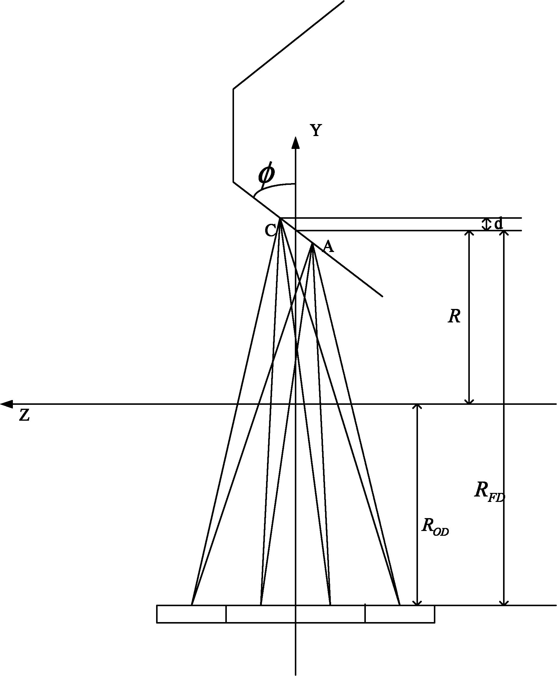
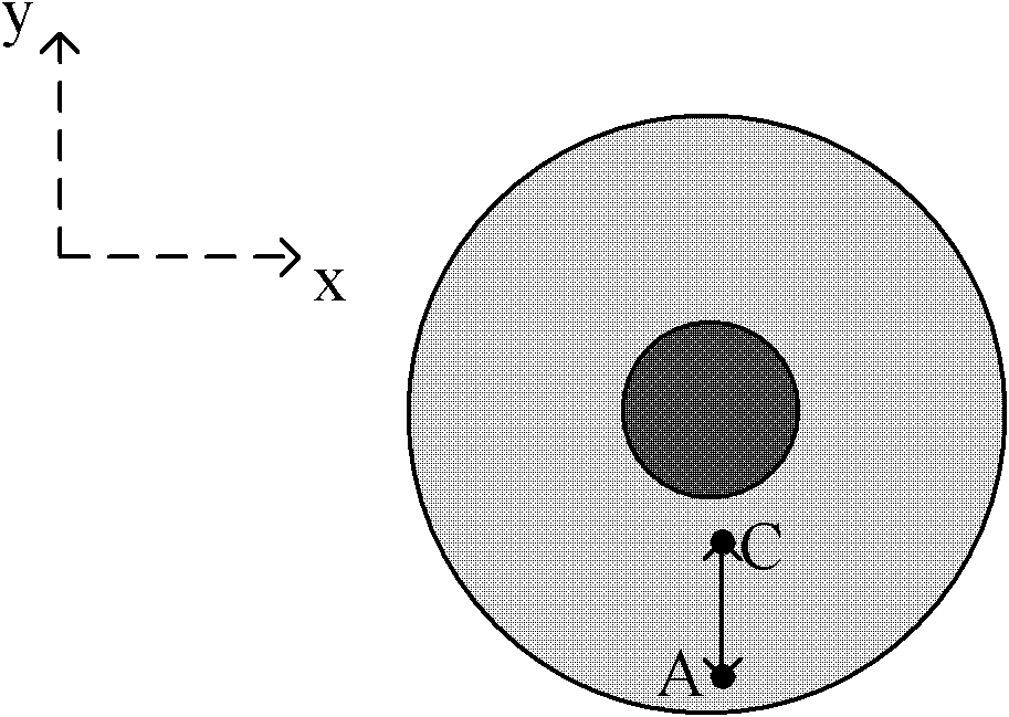
[0047] In the flying focus technology, the focal points A and C are mainly used, and their geometric positions are respectively recorded as:

[0048] A(z-), C(z+).

[0049] The principle of flying focus in the z-axis direction is as follows: figure 1 , where A and C denote two different foci in zDFS, respectively. R represents the radius of rotation of the rack, R FD Indicates the distance from the standard focus position to the detector, R OD Indicates the distance from the center of rotation to the detector, and is represented by R C =R+d and R A =R-d represent the radius of rotation of focus C and focus...


PUM


Abstract

The invention relates to the technical field of CT (computed tomography) and discloses a CT scanning image rebuilding method and a CT scanning image rebuilding device. The method comprises the following steps that scanning data is recombined into data formats required by projection; for each selected target pixel point, passage positions of the projection passing through the target pixel points are calculated; for each selected target pixel point, and layer positions of the projection passing through the target pixel points are determined according to sample points of rays of each type of focus in the z axis; and the obtained passage positions and layer positions of the projection passing through the target pixel points are subjected to weighted accumulation onto the target pixel points. When the CT scanning image rebuilding method and the CT scanning image rebuilding device are utilized, the influence on the z-axis direction resolution ratio caused by the two-step interpolation in the prior art can be avoided.

Description

technical field [0001] The present invention relates to the technical field of CT (Computed Tomography, computer x-ray tomography technology), and more specifically, to a CT scan image reconstruction method and device. Background technique [0002] Z-direction flying focus (zDFS) technology is a technology to improve the resolution of CT (Computed Tomography, computer X-ray tomography) in the z-axis direction. Double the sampling density of data is obtained in one scan, resulting in higher resolution in the z-axis direction. [0003] The three-dimensional back-projection method is a kind of image reconstruction technology in multi-row X-ray CT. It calculates the coordinates of the target reconstruction point projected onto the two-dimensional CT detector in three-dimensional space, and then interpolates on the two-dimensional detector. The interpolated projection value is reversely accumulated to the position of the target reconstruction point, so as to obtain the CT value ...

Claims


Application Information

Patent Timeline
Patent Type & Authority Applications(China)
IPC IPC(8): A61B6/03G06T11/00
Inventor 楼珊珊佟丽霞赵江魏
Owner NEUSOFT MEDICAL SYST CO LTD
Why Eureka
Try Eureka