Deflector apparatus for vehicle

A technology of deflectors and equipment, applied in the direction of vehicle components, roofs, transportation and packaging, etc., which can solve the problem of increased wind noise

Inactive Publication Date: 2012-10-17
AISIN SEIKI KK
View PDF6 Cites 1 Cited by
  • Summary
  • Abstract
  • Description
  • Claims
  • Application Information

AI Technical Summary

Problems solved by technology

Thus, in the case of overextension of the deflection elem...

Method used


Image

  • Deflector apparatus for vehicle
  • Deflector apparatus for vehicle
  • Deflector apparatus for vehicle

Examples


Embodiment Construction

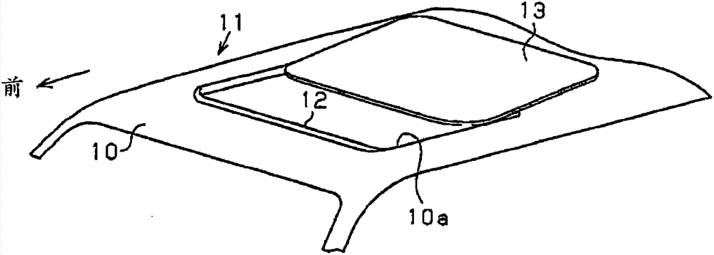
[0028] Embodiments will be described with reference to the drawings. In an embodiment, directions and orientations such as left, right, front, rear, top and bottom correspond to directions and orientations of the vehicle in which the deflector device for the vehicle is mounted. as in figure 1 As illustrated in , a roof 10 serving as a roof portion of a vehicle includes, for example, a roof opening 10 a serving as an opening and having a substantially rectangular shape. The sunroof apparatus 11 installed at the roof 10 includes a deflector 12 arranged and supported at the front edge (front inner peripheral edge) of the roof opening 10 a. The deflector 12 is used as a deflector device for a vehicle. For example, the sunroof arrangement 11 also comprises a movable panel 13 which has substantially a rectangular shape and is formed of a glass plate. The movable panel 13 moves in the longitudinal direction of the vehicle to thereby open and close the roof opening 10a.

[0029] T...


PUM


Abstract

A deflector apparatus for a vehicle (12) includes a fixed frame (21), a movable frame (22) positioned at an upper side of the fixed frame and being rotatable between a raised position and a retracted position, a mesh member (23) connected to the fixed frame and the movable frame and brought to a raised state and a retracted state, and a spring member. The spring member includes a sliding portion (44) fitted to a guide groove (51) formed at the movable frame and slidably making contact with the guide groove to transmit a biasing force of the spring member in a state where the movable frame is rotating. The spring member further includes an engagement portion (46) engaging with the movable frame when the movable frame is in the raised position. The movable frame is configured to be maintained at the raised position by the engagement with the engagement portion of the spring member.

Description

technical field [0001] The present invention generally relates to deflector arrangements for vehicles. Background technique [0002] A known deflector device for a vehicle is disclosed, for example, in US6834914 (hereinafter referred to as reference 1). The deflector device (wind deflector) disclosed in Reference 1 is installed at the front edge of a roof opening formed at the roof of the vehicle. In case the lid for opening and closing the roof opening in a sliding roof system is opened, the deflector device is raised above the vehicle roof. The deflector device includes a base member extending along the front edge of the roof opening and secured to a mounting frame extending along the front edge of the roof opening. The deflector device further comprises raising means rotatably connected to the base part via pivot means so as to be movable between a retracted position and a raised position. The raising device is biased into a raised position by a resilient member. Furt...

Claims


Application Information

Patent Timeline
IPC IPC(8): B60J7/22
CPCB60J7/22
Inventor 深见清澄井田博之矶部聪
Owner AISIN SEIKI KK
Why Eureka
Try Eureka