Joint for torque transmission, and electric power steering device

A technology for torque and transmission components, applied in the field of torque transmission joints and electric power steering devices, can solve problems such as abnormal noise, and achieve the effect of suppressing abnormal noise

Inactive Publication Date: 2018-11-09
NSK LTD
View PDF9 Cites 1 Cited by
  • Summary
  • Abstract
  • Description
  • Claims
  • Application Information

AI Technical Summary

Problems solved by technology

Therefore, abnormal noise may be generated when reversing the rotation direction of the rotary shaft

Method used


Image

  • Joint for torque transmission, and electric power steering device
  • Joint for torque transmission, and electric power steering device
  • Joint for torque transmission, and electric power steering device

Examples


Embodiment Construction

[0117] [the first example of embodiment]

[0118] pass Figure 1-14 A first example of an embodiment of the present invention will be described.

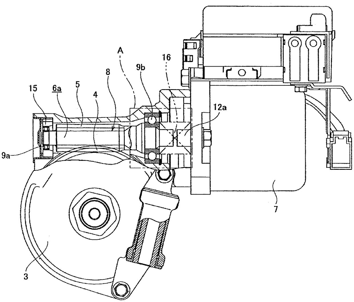
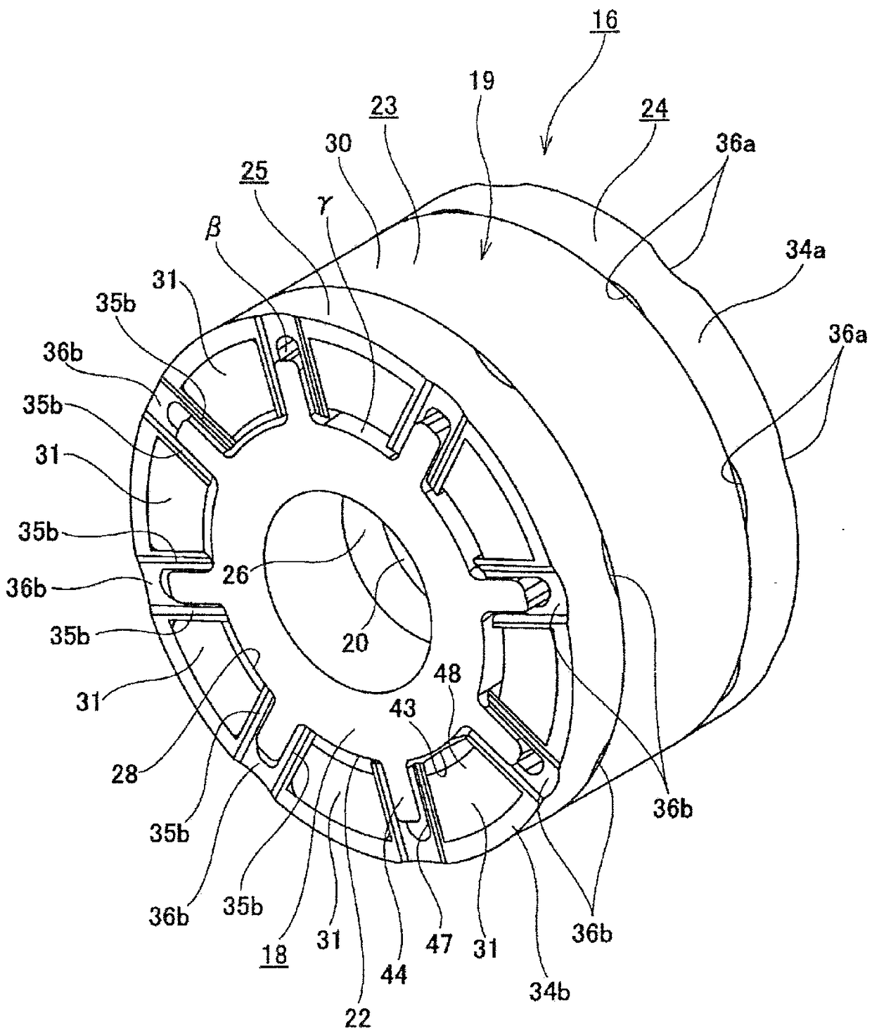
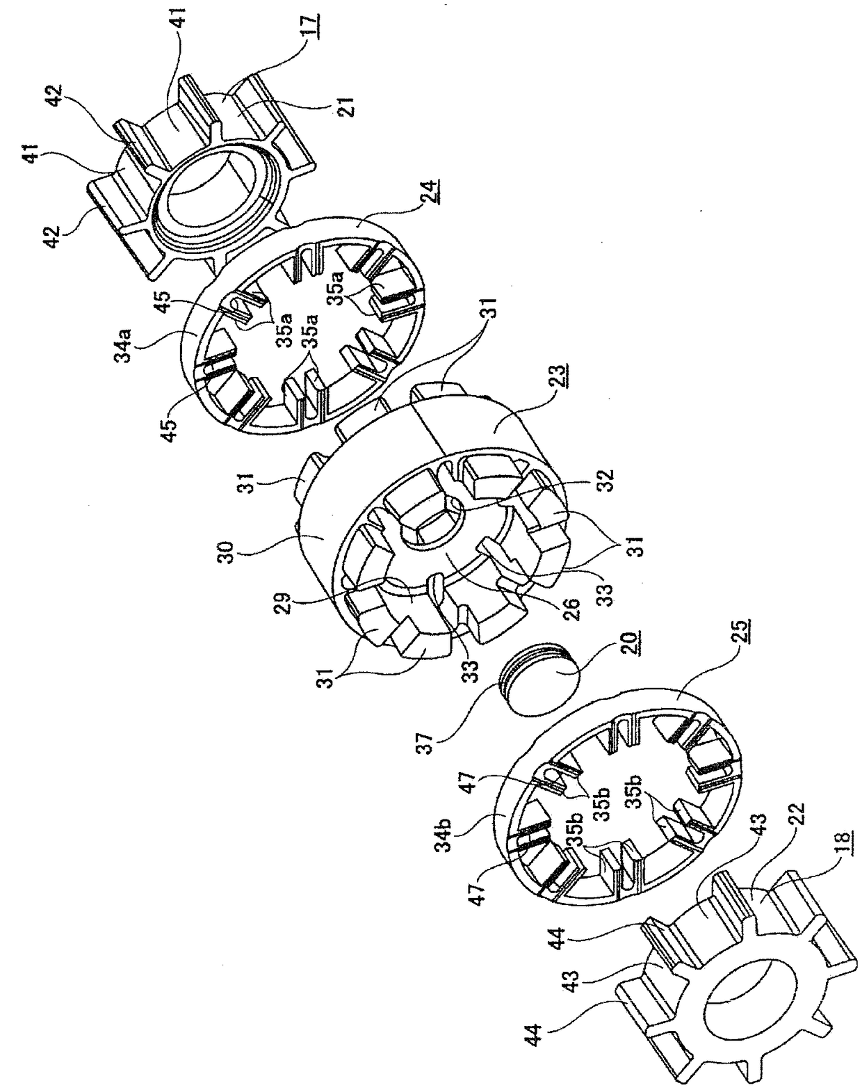
[0119] The electric power steering device of this example is the same as the above-mentioned Figure 23-24 In the conventional structure shown, the steering wheel 1 is attached to the rear end of the steering shaft 2 , the front end of the steering shaft 2 is rotatably supported in the housing 3 , and the worm wheel 4 is fixed to the part driven by the steering shaft 2 . A worm tooth 5 meshing with the worm wheel 4 is provided at an axially intermediate portion of the worm shaft 6a. Both ends in the axial direction of the worm 8 rotationally driven by the electric motor 7 are rotatably supported in the housing 3 by a pair of rolling bearings (ball bearings in the illustrated example) 9a, 9b. Further, the worm gear 5 provided on the worm shaft 6a is pressed against the worm wheel 4 by providing the preload imparting mechanism 15 be...


PUM


Abstract

A drive-side part having recesses and protrusions engages in a cup-side first part having recesses and protrusions, and the drive-side part having recesses and protrusions engages in a portion of a cup-side third part having recesses and protrusions that is positioned farther toward one axial side than a dividing wall part, such that interposed therebetween is a circumferential-direction gap larger than a circumferential-direction gap formed in the engagement part of the drive-side part having recesses and protrusions and the cup-side first part having recesses and protrusions. A driven-side part having recesses and protrusions engages with a cup-side second part having recesses and protrusions, and the driven-side part having recesses and protrusions engages in a portion of the cup-side third part having recesses and protrusions that is positioned farther toward another axial side than the dividing wall part, such that interposed therebetween is a circumferential-direction gap largerthan a circumferential-direction gap formed in the engagement part of the driven-side part having recesses and protrusions and the cup-side second part having recesses and protrusions. At least one portion of the dividing wall part is disposed between the axial end faces of a drive-side transmission member and a driven-side transmission member.

Description

technical field [0001] For example, the torque transmission joint according to the present invention is incorporated into various mechanical devices to transmit torque between a drive shaft and a driven shaft. For example, the electric power steering device of the present invention is used as a steering device of an automobile, and by using an electric motor as an auxiliary power source, the force required by the driver to operate the steering wheel is reduced. Background technique [0002] A power steering device is widely used as a device for reducing the force required by the driver to operate the steering wheel when imparting a steering angle to the steering wheels (except for special vehicles such as forklifts, usually the front wheels). In addition, as such a power steering device, an electric power steering device using an electric motor as an auxiliary power source has become popular in recent years. Various structures of such an electric power steering device are k...

Claims


Application Information

Patent Timeline
Patent Type & Authority Applications(China)
IPC IPC(8): F16D3/74B62D5/04F16D3/50
CPCB62D5/0409F16D3/54F16D3/68F16D3/74B62D5/0454F16H1/16
Inventor 大泽亮
Owner NSK LTD
Why Eureka
Try Eureka