Waste gate valve control method and control device

一种废气旁通阀、控制方法的技术,应用在电气控制、电动发动机控制自动控制、燃气轮机装置等方向,能够解决易产生异常噪音、阀体振动等问题,达到抑制异常噪音的效果

Active Publication Date: 2018-08-28
NISSAN MOTOR CO LTD
View PDF8 Cites 1 Cited by
  • Summary
  • Abstract
  • Description
  • Claims
  • Application Information

AI Technical Summary

Problems solved by technology

[0005] Therefore, when the engine is idling in a cold state where the exhaust pulsation becomes large, the valve body vibrates due to the above-mentioned gap, and abnormal noise is likely to be generated.

Method used


Image

  • Waste gate valve control method and control device
  • Waste gate valve control method and control device
  • Waste gate valve control method and control device

Examples


Embodiment Construction

[0016] Hereinafter, an embodiment of the present invention will be described in detail based on the drawings.

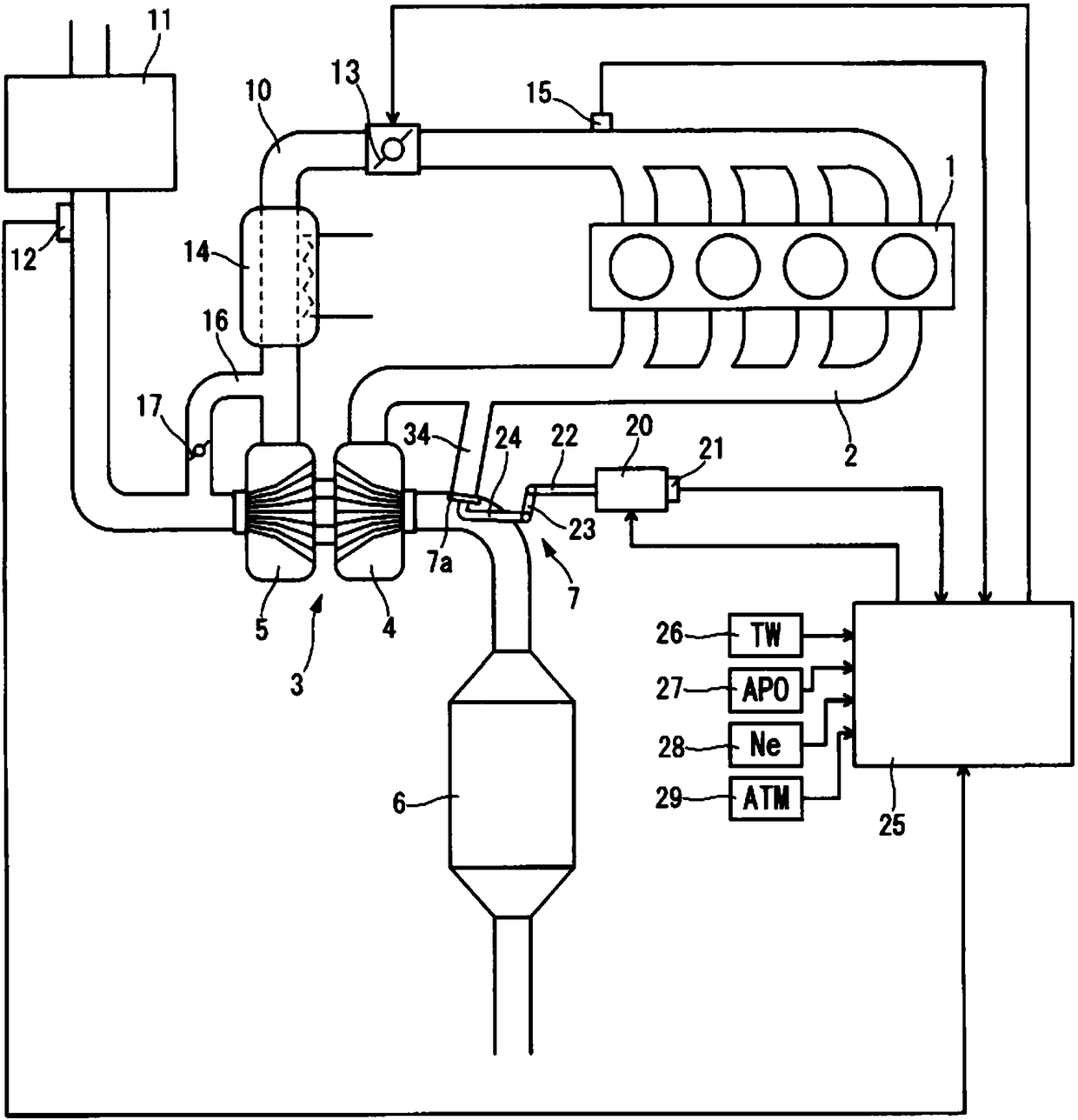
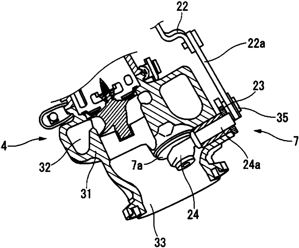
[0017] figure 1 It is a configuration explanatory diagram showing a system configuration of an embodiment of the present invention, in which an exhaust turbine 4 of a turbocharger 3 is arranged in an exhaust passage 2 of an internal combustion engine 1 which is a spark ignition type gasoline internal combustion engine, and an exhaust turbine 4 of a turbocharger 3 is arranged on the downstream side thereof. For example, the catalytic converter 6 using a three-way catalyst. An exhaust muffler (not shown) is provided further downstream of the exhaust passage 2, and the exhaust passage 2 is opened to the outside through the exhaust muffler. The exhaust turbine 4 is provided with a wastegate 7 for supercharging pressure control. In addition, the internal combustion engine 1 is, for example, of a direct-injection type, and has a fuel injection valve (not shown) for injec...


PUM


Abstract

A waste gate valve (7) of a turbocharger (3) is fully open during idling after warm-up is complete in order to reduce exhaust resistance, and during cool-down idling when a cooling water temperature (TW) is below a threshold value (TW1), the waste gate valve (7) is open-loop controlled to an intermediate opening degree that is smaller than fully open. The ignition time is delayed for catalyst warm-up. When the cooling water temperature (TW) reaches (t3) the threshold value (TW1), the opening degree of the waste gate valve (7) is set to fully open. When the accelerator opening degree (APO) becomes large (t4) before warm-up is complete, control of the opening degree is released.

Description

technical field [0001] The invention relates to the opening control of a wastegate valve provided in a turbocharger of an internal combustion engine. Background technique [0002] A turbocharger used for supercharging an internal combustion engine generally has a wastegate valve in a turbine section that bypasses part of the exhaust gas flow without passing through the turbine wheel for supercharging pressure control. Patent Document 1 discloses, as a drive mechanism for opening and closing the wastegate valve, a so-called swing-type structure in which linear motion of the rod of the electric actuator is converted into rotation via a link. The rotational movement of the shaft causes the poppet type valve body supported by the tip of the arm portion fixed to the rotational shaft to swing. [0003] In the wastegate described above, as described in Patent Document 1, there is a slight gap between a part of the drive mechanism, for example, between the tip of the arm and the po...

Claims


Application Information

Patent Timeline
Patent Type & Authority Applications(China)
IPC IPC(8): F02B37/18F02B37/12
CPCF02B37/18F02D41/068F02D41/08F02D41/0007F02B37/186F02D2250/18F02P5/045F02P5/1508F02D37/02F02D2200/602F02D41/086Y02T10/12Y02T10/40F02P5/04F01D17/105F02C6/12F05D2220/40
Inventor 森川雅司远藤翼久保田充彦
Owner NISSAN MOTOR CO LTD
Why Eureka
Try Eureka