Power transmission mechanism and multi-shaft drive device

A technology of power transmission mechanism and connecting mechanism, which is applied in the direction of transmission, mechanical drive clutch, special position of the vehicle, etc., can solve the problem of a large number of motors, and achieve the effect of suppressing the occurrence of abnormal noise and reducing the amount of wear and tear.

Inactive Publication Date: 2015-06-24
NHK SPRING CO LTD
View PDF5 Cites 0 Cited by
  • Summary
  • Abstract
  • Description
  • Claims
  • Application Information

AI Technical Summary

Problems solved by technology

[0003] In order to independently drive a plurality of movable parts, it is conceivable to connect one motor to each output shaft connected to the movable part, but this increases the number of motors

Method used


Image

  • Power transmission mechanism and multi-shaft drive device
  • Power transmission mechanism and multi-shaft drive device
  • Power transmission mechanism and multi-shaft drive device

Examples


no. 2 Embodiment approach

[0088] Next, pass Figure 10 and Figure 11 A second embodiment of the present invention will be described.

[0089] The multi-axis driving device of the second embodiment differs in that a slide cam (selector member) 70 is used instead of the dial cam 50 of the first embodiment, and the shape of the box is also different corresponding to the slide cam 70 .

[0090] Figure 10 and Figure 11 It is a perspective view and a plan view of the multi-axis drive device concerning 2nd Embodiment. In these figures, reference numeral 80 is a case fixed to the upper portion of the motor 10, and the opening of the case 80 is covered with a cover not shown. On the side of box 80 (in Figure 11 A plurality of half-cut cylindrical gear holder parts 62 are formed on the side surfaces on both sides in the X direction in the middle. In this case, the gear holder portion 62 is Figure 11 Among them, two are formed on the right side, and one is formed on the left side. In these gear holder...


PUM


Abstract

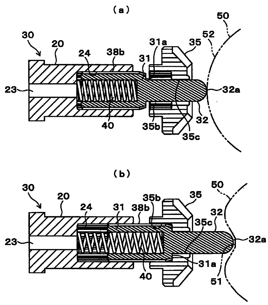
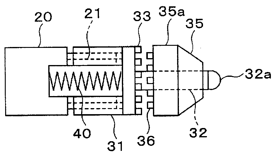
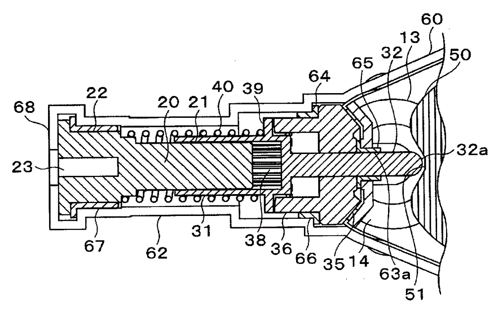
Force of used spring can be weak, wear amount of power transmission member (gear or the like) can be reduced, and generation of strange noises can inhibited. When the dial cam 50 is rotated and the recess 51 of the outer peripheral surface 52 faces the front end portion 32a of the pin 32 of the connection shaft 31, the connection shaft 31, which is biased by the force of the coil spring 40, is connected to the bevel gear 35, which engages with the bevel gear 14 and is rotated, via the clutch teeth 33 and 36. Thus, the connection shaft 31 is rotated, and the output shaft 20 is rotated together with the connection shaft 31. That is, the power of the motor 10 is transmitted to the output shaft 20. Since the coil spring 40 is used for connecting the connection shaft 31 to the bevel gear 35, the force of the coil spring 40 can be reduced.

Description

technical field [0001] The present invention relates to a power transmission mechanism for connecting / disconnecting power to and from an output transmission member such as an output shaft, and a multi-shaft drive device using the same. Background technique [0002] For example, in a vehicle seat, it is possible to adjust the position of multiple parts such as sliding in the front-rear direction or the vertical movement of the seat height, or the reclining of the seat back (backrest), and the form that can be adapted to the body shape and posture of the occupant. There are many structures. Adjustment of these movable parts is performed manually, but as a more convenient structure, an electric seat that is driven and adjusted by a motor is provided. [0003] In order to independently drive a plurality of movable parts, it is conceivable to connect one motor to each output shaft connected to the movable part, but this increases the number of motors. Therefore, it is efficient...

Claims


Application Information

Patent Timeline
Patent Type & Authority Patents(China)
IPC IPC(8): F16D11/04B60N2/44F16D11/08F16D11/10B60N2/90
CPCB60N2/0296F16D11/04F16D2023/123Y10T74/19088F16D11/08F16D11/10F16H37/065
Inventor 重松良平村上谦二中岛洁平田贵史藤井贵广饭野信次
Owner NHK SPRING CO LTD
Why Eureka
Try Eureka