Rail clamping device

A rail-clamping and wedge-shaped technology, applied in transportation and packaging, brakes interacting with the rails, railway car body parts, etc. , the effect of expanding the scope of application

Inactive Publication Date: 2012-10-17
上海耐斯特液压设备有限公司
View PDF6 Cites 8 Cited by
  • Summary
  • Abstract
  • Description
  • Claims
  • Application Information

AI Technical Summary

Problems solved by technology

The disadvantage of the existing hoist traction device is that it needs to be dragged and pulled at the front and rear ends when used on a slope track, and the operation coordination is difficult and the safety is not high

Method used


Image

  • Rail clamping device
  • Rail clamping device
  • Rail clamping device

Examples


Embodiment Construction

[0022] The present invention will be further described below in conjunction with the accompanying drawings.

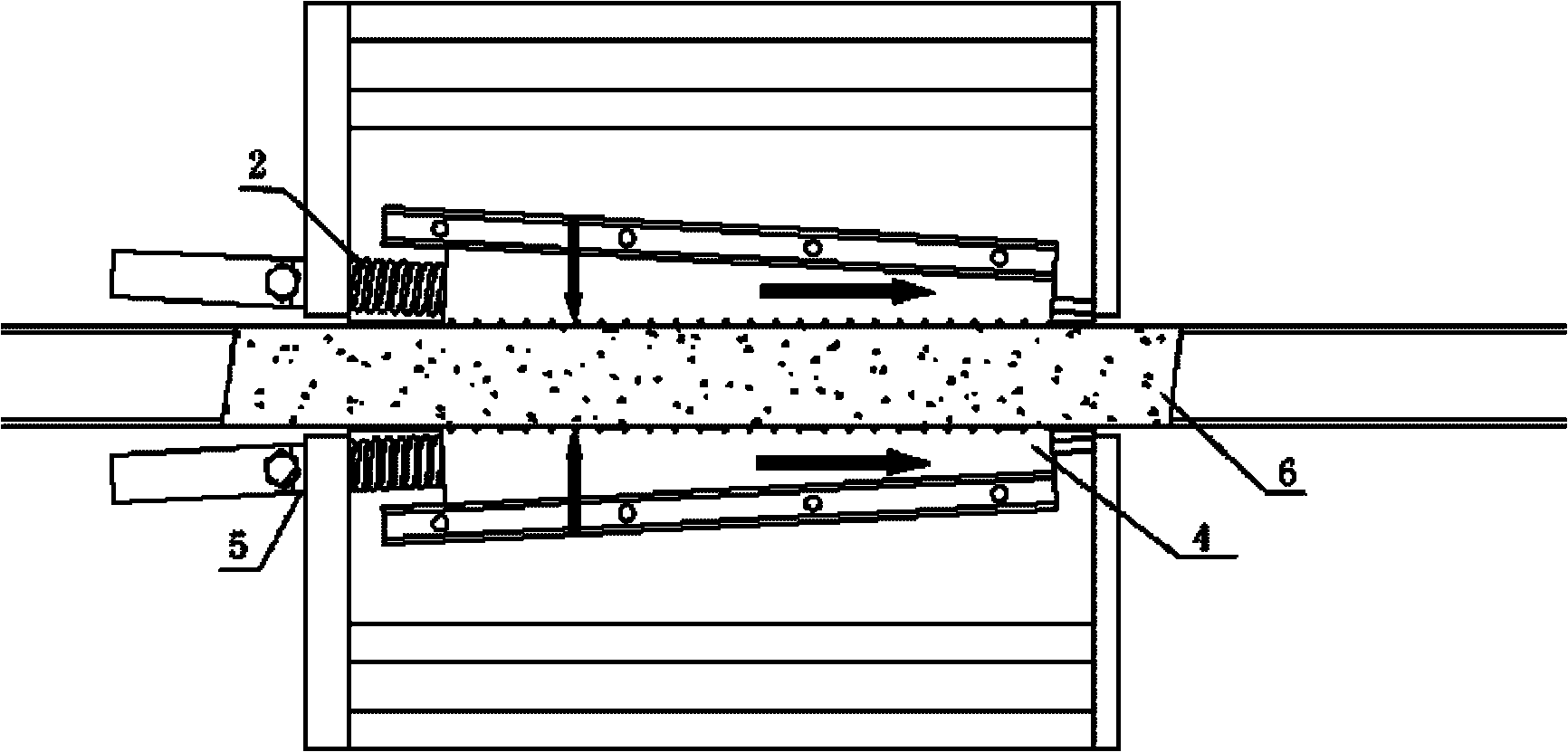
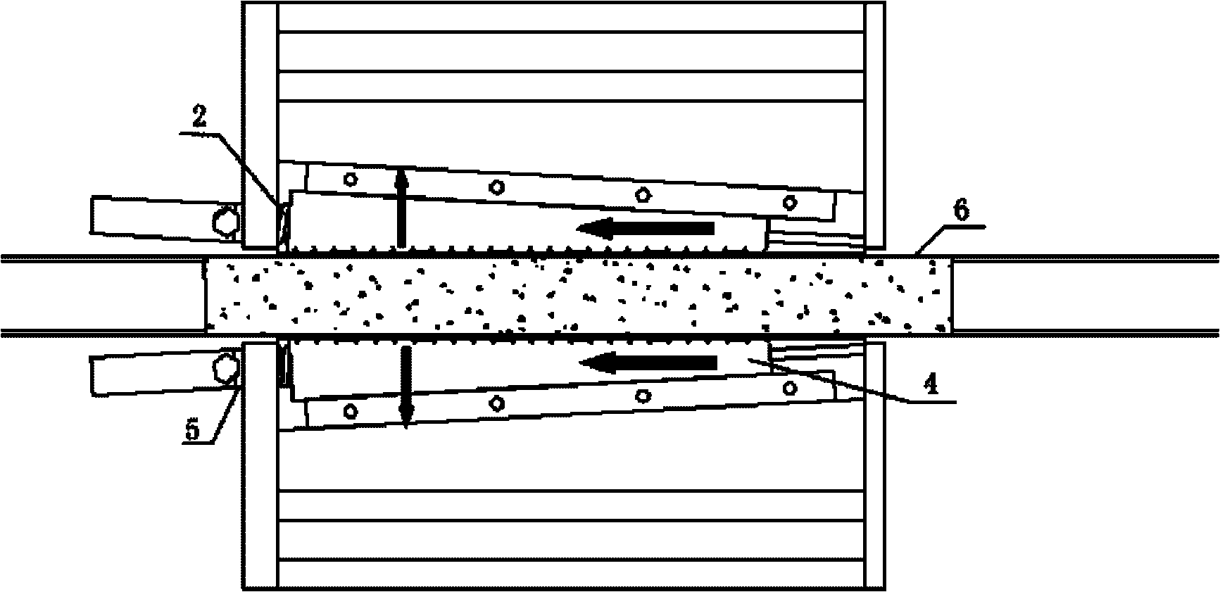
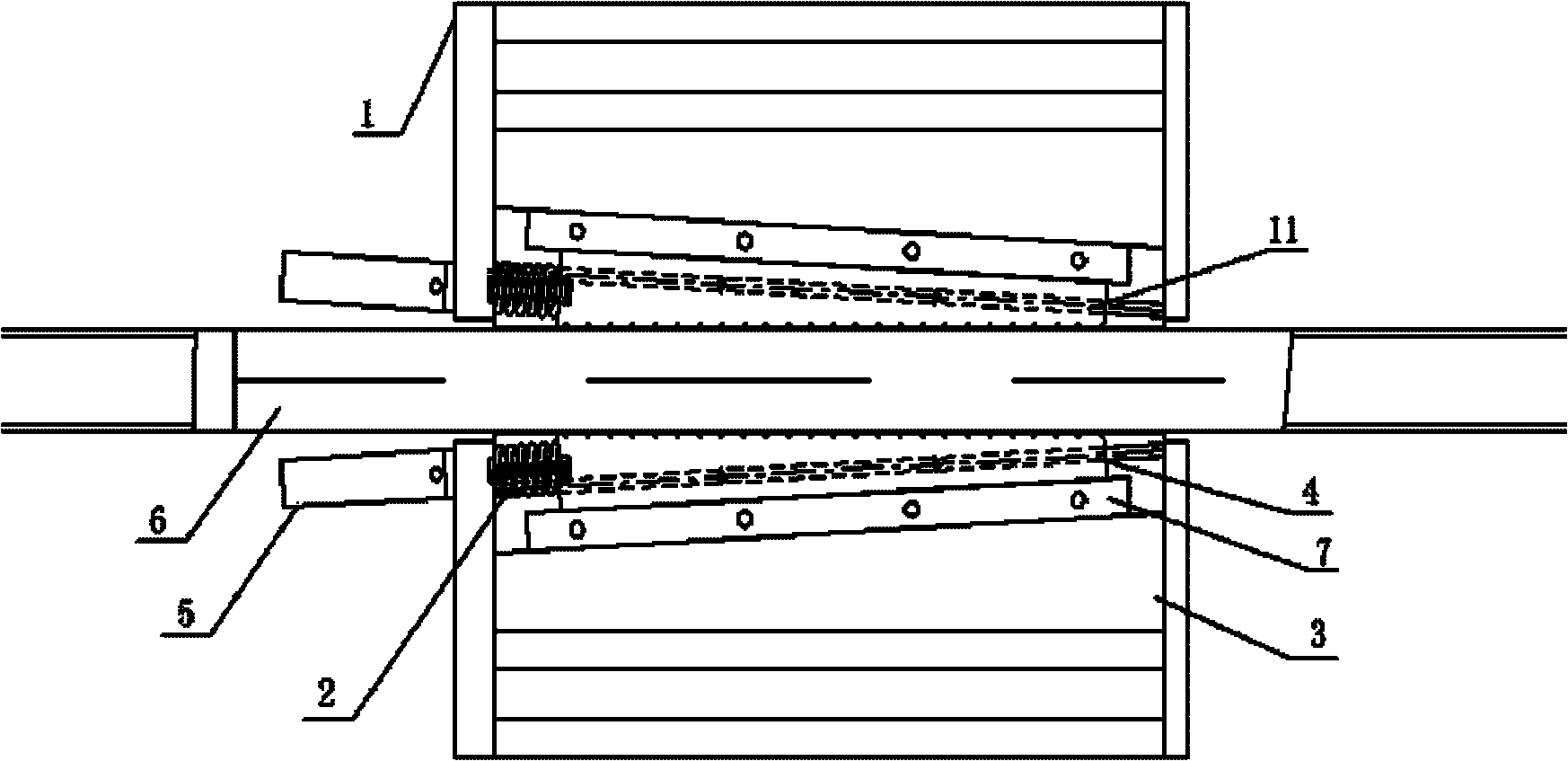
[0023] Such as Figure 1-3 , is a schematic diagram of the structure of the rail clamping device, the rail clamping device includes a housing 1, the inside of the housing 1 is a wedge-shaped base 3, the inside of the wedge-shaped base 3 is a wedge-shaped block 4, and the wedge-shaped block 4 and the wedge-shaped base 3 are arranged Slide block 7. As can be seen in the figure, there are two wedge-shaped bases 3, wedge-shaped blocks 4 and stoppers 7, and every two wedge-shaped bases, wedge-shaped blocks and sliding pads are mirror images. The wedge block 4 is equipped with a sliding guide 11 . A back-moving spring 2 is installed on the top of one side of each wedge block 4 . A single-acting oil cylinder 5 is installed outside the housing on which the return spring 2 is installed. The track 6 passes between the two wedge blocks, and the track equipment is stopped by t...


PUM


Abstract

The invention discloses a rail clamping device. The rail clamping device comprises a shell. The rail clamping device is characterized in that a wedged base is arranged in the shell; a wedged block is arranged in the wedged base; a sliding cushion block is arranged between the wedged block and the wedged base; the wedged block is driven by an oil cylinder; and a spring is reset. With the adoption of the structure provided by the invention, the rail clamping device can be applied to a slope rail, no slipping occurs, and equipment can be still for a long period; not only in a normal state but also in a condition that the equipment is suddenly switched off or has a fault, the rail clamping device can lock a rail in a safe and reliable manner; and the rail clamping device enables the equipment to go forwards or backwards on the premise of ensuring the security in advance under the control of a ruled program. Compared with the traditional rail clamping device, the rail clamping device provided by the invention has the following remarkable characteristics: firstly, the rail can be ensured to be locked at any time in the safe and reliable manner; secondly, the rail clamping device can be applied to a flat ground or a slope; thirdly, the equipment goes forwards and backwards with the adoption of the rail clamping device; and fourthly, the program can be set and operated by a hydraulic oil cylinder in a controlled manner.

Description

technical field [0001] The invention relates to a device running on a rail and capable of assisting the stopping and moving of equipment transported on the rail, belonging to the field of machinery, in particular to a rail clamping device. Background technique [0002] In the industrial fields such as steel and heavy-duty machinery, the manufacture and assembly of many equipment and the transportation of materials need to be carried out on rails. For example, some large components need to be constructed, spliced, and closed on slopes. During the construction process, some auxiliary equipment is required to move and stop on the track of the slope. And when stopping, it is necessary to make the equipment firmly fixed on the slope by means of external force. [0003] When the weight of the equipment running on the slope is heavy, it needs to be limited by corresponding external force to make it stop. The working principle of the rail clamping device is to clamp the track so t...

Claims


Application Information

Patent Timeline
Patent Type & Authority Applications(China)
IPC IPC(8): B61H7/12
Inventor 郁明亮金君李磊
Owner 上海耐斯特液压设备有限公司
Why Eureka
Try Eureka