Composite buffer for crane

A composite, buffer technology, applied in the direction of shock absorbers, shock absorbers, mechanical equipment, etc., can solve the problems of increasing the production cost of the crane, increasing the raw materials of the crane, increasing the volume of the crane, etc., and achieves light weight, low cost, and high production. low cost effect

Active Publication Date: 2015-05-06
昌乐县东田聚氨酯厂
View PDF5 Cites 1 Cited by
  • Summary
  • Abstract
  • Description
  • Claims
  • Application Information

AI Technical Summary

Problems solved by technology

At present, the types of buffers mainly include spring buffers and hydraulic buffers. With the continuous development of the crane industry, large-tonnage cranes are becoming more and more common. If the performance is required, the size must be increased, which not only increases the amount of raw materials and increases the production cost, but also requires the crane to leave a large installation space for the buffer, which will increase the volume of the crane. Correspondingly, the raw materials for manufacturing the crane will be increased, and the production cost of the crane will also be increased.

Method used


Image

  • Composite buffer for crane
  • Composite buffer for crane

Examples


Embodiment 1

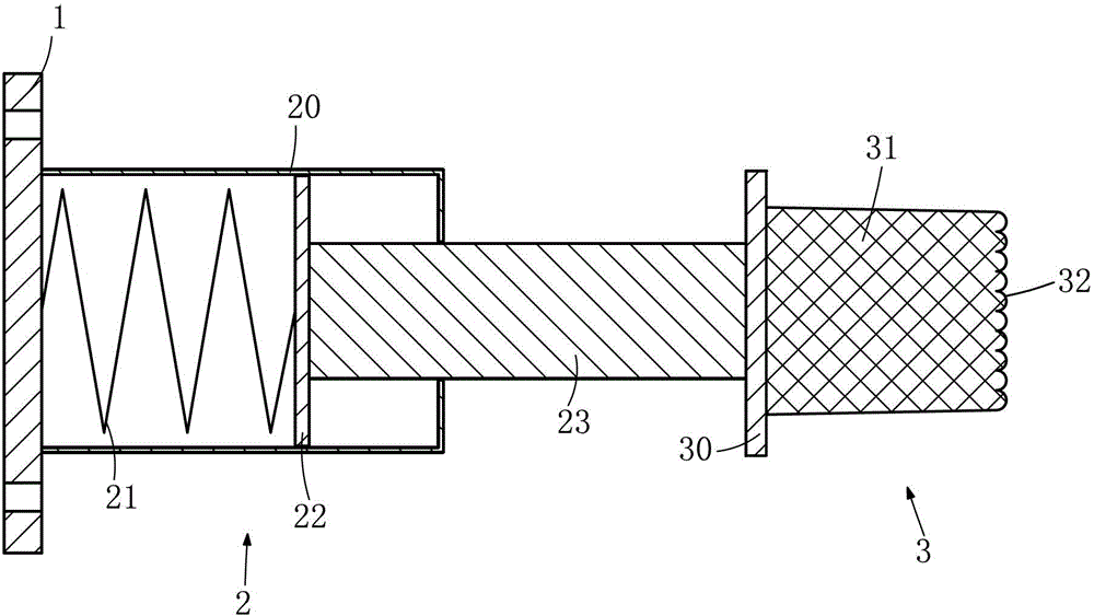
[0017] Such as figure 1 As shown, a composite buffer for a crane includes a base 1, on which a primary buffer device 2 is arranged, and the primary buffer device 2 includes a housing 20 fixed on the base 1, and a spring 21 is arranged in the housing 20 , one end of the spring 21 is fixed on the base 1, the other end of the spring 21 is connected with a piston 22, the other side of the piston 22 is provided with a piston rod 23, and one end of the piston rod 23 passes through the housing 20; the composite buffer also includes The secondary buffer device 3 is connected with the end of the piston rod 23 exposed outside the casing 20 . When a collision occurs, the spring 21 inside the primary buffer device 2 is first compressed to act as a buffer. When the spring 21 is completely compressed and the secondary buffer device 3 is in contact with the housing of the primary buffer device 2, the The first-stage buffer device 3 is compressed to further play a buffering role. The combine...

Embodiment 2

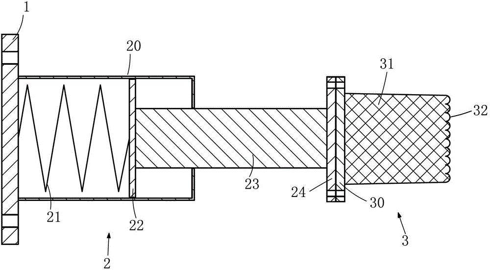
[0021] Such as figure 2 As shown, a composite buffer for a crane has a structure basically the same as that of Embodiment 1, the difference is that a connection plate 24 is provided at the end where the piston rod 23 passes through the housing 20, and the secondary buffer device 3 and the connection plate 24 connections make the installation of the composite buffer more convenient, and it is also very convenient to replace the primary buffer device 2 or the secondary buffer device 3, prolonging the service life of the composite buffer.

[0022] Working principle of the present invention: when a collision occurs, the secondary buffer device 3 is first stressed, and the secondary buffer device 3 transmits the compression force to the piston 22 through the piston rod 23, and the piston 22 compresses the spring 21. When the spring 21 is completely compressed At this time, the connecting bottom plate 30 of the secondary buffer 3 is in contact with the shell of the primary buffer 2...


PUM


Abstract

The invention discloses a composite buffer for a crane and relates to the technical field of buffer equipment. The composite buffer comprises a base, wherein a primary buffer device is arranged on the base and comprises a shell which is fixed on the base; a spring is arranged in the shell; one end of the spring is fixed on the base, and the other end of the spring is connected with a piston; the other side of the piston is provided with a piston rod; one end of the piston rod penetrates out of the shell; the composite buffer also comprises a secondary buffer device; and the secondary buffer device is connected with one end of the piston rod which is exposed out of the shell. According to the composite buffer for the crane, the requirement of a large-tonnage crane on the buffer performance can be met, and the composite buffer is small in size, low in production cost, long in service life, wide in application range and suitable for popularization and application, can replace various buffers of different specifications and is an innovative product in the field.

Description

technical field [0001] The invention relates to the technical field of buffer equipment, in particular to a composite buffer for a crane. Background technique [0002] Due to the heavy weight of the crane itself, when the crane's running limiter or braking device fails, due to inertia, the crane or trolley running to the end will collide with the set stopper at the end of the run, serious It will cause major safety accidents. The purpose of setting up the buffer is to absorb the running energy of the crane or trolley, and play the role of buffering, vibration reduction and ensuring safety. At present, the types of buffers mainly include spring buffers and hydraulic buffers. With the continuous development of the crane industry, large-tonnage cranes are becoming more and more common. If the performance is required, the size must be increased, which not only increases the amount of raw materials and increases the production cost, but also requires the crane to leave a large i...

Claims


Application Information

Patent Timeline
Patent Type & Authority Patents(China)
IPC IPC(8): B66C7/16F16F7/104
Inventor 鞠卫东
Owner 昌乐县东田聚氨酯厂
Why Eureka
Try Eureka