Washing machine

A washing machine and water tank technology, applied in the field of washing machines, can solve the problem of difficulty in detecting whether the water tank 82 is fixed and maintained.

Inactive Publication Date: 2012-10-17
PANASONIC CORP
View PDF7 Cites 6 Cited by
  • Summary
  • Abstract
  • Description
  • Claims
  • Application Information

AI Technical Summary

Problems solved by technology

As a result, it is difficult to distinguish from the situation where the fixing bolt 85 is still installed and the shaking is small, that is, it is very difficult to detect whether the water tank 82 is fixed and held.

Method used


Image

  • Washing machine
  • Washing machine
  • Washing machine

Examples


Embodiment approach

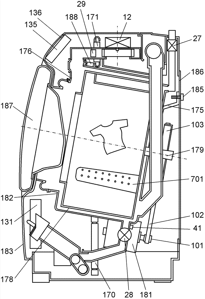
[0036] figure 1 It is a sectional view of the washing machine according to the embodiment of the present invention.

[0037] Such as figure 1 As shown, the washing machine of this embodiment includes at least a main body 183 , a water tank 182 , a drum 178 , fixing bolts 185 , a water supply valve 27 , a motor 181 , and a control unit 131 .

[0038] The water tank 182 is provided swingably inside the main body 183, and the direction of the rotation shaft 179 is inclined downward from the horizontal direction from the front side of the opening toward the rear side serving as the bottom. A drum 178 is rotatably provided inside the water tank 182 . Further, the drum 178 is connected to a motor 181 attached to a lower portion on the back side which is the bottom of the water tank 182 via a motor pulley 101 , a belt 102 , a drive pulley 103 , and the like. Further, the drum 178 is rotationally driven by the motor 181 in the forward rotation and reverse rotation directions arou...


PUM


Abstract

The invention provides a washing machine comprising a body (183), a water channel (182), a roller (178) which can be rotatably and freely born in the water channel (182), a motor (181), fixed bolts (185) for fixing the water channel (182) and the body (183), a water-supply valve (41) for supply water to the water channel (182), and a control unit (131), wherein when the control unit (131) supplies water to the water channel (182) to the specified water level, the roller (178) rotates; and based on the detection result of an acceleration detection unit (39), the fixed bolts (185) are determined whether the fixed bolts (185) are dismounted.

Description

technical field [0001] The present invention relates to a washing machine that swingably supports a drum and a water tank for storing laundry in a main body. Background technique [0002] Conventionally, for example, Japanese Unexamined Patent Application Publication No. 2010-57848 (hereinafter referred to as "Patent Document 1") discloses a washing machine including a vibration-proof structure that prevents vibration accompanying the rotation of the drum from being transmitted to the main body. [0003] Next, use Figure 9 , the structure of the conventional washing machine shown in Patent Document 1 will be described. [0004] Figure 9 It is a sectional view of the conventional washing machine. [0005] Such as Figure 9 As shown, the conventional washing machine includes at least a main body 83 , a drum 78 , a water tank 82 , a baffle 70 , a suspension 71 and a control unit 31 . [0006] The water tank 82 is swingably supported from below by the baffle plate 70 in the ...

Claims


Application Information

Patent Timeline
Patent Type & Authority Applications(China)
IPC IPC(8): D06F37/00D06F33/02
Inventor 八木知隆上野圣一住田胜章吉田直人
Owner PANASONIC CORP
Why Eureka
Try Eureka