
Solid-state imaging apparatus, method for manufacturing same, and electronic system

A technology of a solid-state imaging device and a manufacturing method, which are applied to parts of a television system, electric solid-state devices, radiation control devices, etc.

Inactive Publication Date: 2012-10-17
SONY CORP
View PDF8 Cites 14 Cited by
  • Summary
  • Abstract
  • Description
  • Claims
  • Application Information

AI Technical Summary

Problems solved by technology

Since the size of the solid-state imaging device 610 decreases with the size of the solid-state imaging device, the light transmitted through the lens 661 and the IRCF 662 tends to be reflected by the bonding wiring 630 and is incident on the imaging region 612 of the solid-state imaging device 610, thereby more easily causing the above-mentioned flare

Method used


Image

  • Solid-state imaging apparatus, method for manufacturing same, and electronic system
  • Solid-state imaging apparatus, method for manufacturing same, and electronic system
  • Solid-state imaging apparatus, method for manufacturing same, and electronic system

Examples


no. 2 example

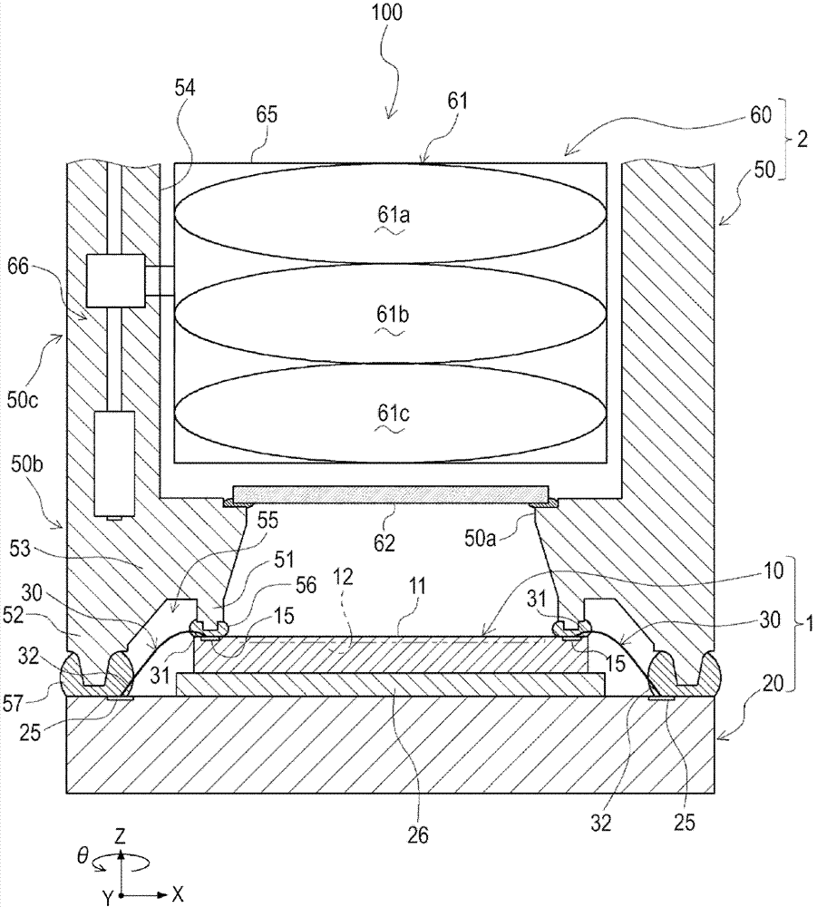
[0086] The structure of the legs of the second embodiment will be described below. The same parts as those of the above-described embodiment are denoted by the same reference numerals, and descriptions thereof are appropriately omitted. This embodiment differs from the above-mentioned embodiments in that the protruding portion formed at the lower end of the first leg portion 51 has two-stage convex shapes with different protruding heights.

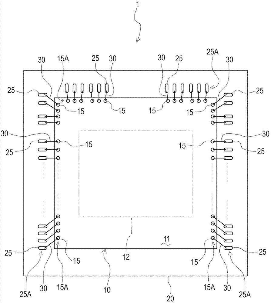
[0087] The leg structure of the present embodiment is preferably used when some pads 15 on the solid-state imaging device 10 are pads called dummy pads 15b. In this embodiment, the pads 15 are thus classified into connection pads 15a and empty pads 15b, wherein the connection pads 15a are connected to the bonding wiring 30, and the empty pads 15b are non-connecting pads not connected to the bonding wiring 30. connection pad. That is, if Image 6 As shown, in this embodiment, the plurality of pads 15 formed on the imaging surface 11 of t...


PUM


Abstract

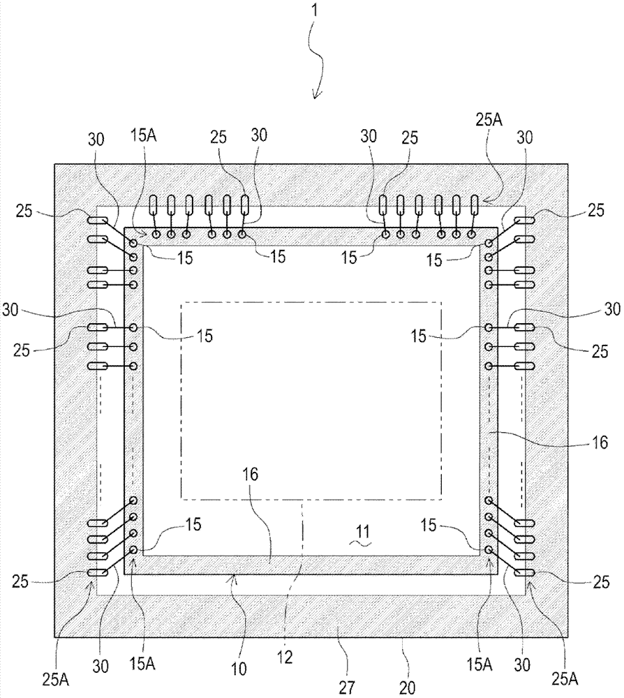
The invention relates to a solid-state imaging apparatus, a method for manufacturing the same, and an electronic system. The solid-state imaging apparatus includes: a solid-state imaging device mounted on a substrate; a bonding wire that electrically connects a pad formed on the solid-state imaging device to a lead island formed on the substrate; a frame member that has a frame-like shape and surrounds side portions of the solid-state imaging device; and a light-transmissive optical member so accommodated in the frame member that the optical member faces an imaging surface of the solid-state imaging device, wherein the frame member has a leg portion extending from the side where the optical member is present toward the imaging surface, and the frame member is integrally fixed to the solid-state imaging device with an end of the bonding wire that is connected to the pad covered with the leg portion. The solid-state imaging apparatus restrains solar flare caused by reflected light of the bonding wire and realizes reduction of size.

Description

[0001] Cross References to Related Applications [0002] The present application contains subject matter related to the disclosure of Japanese Priority Patent Application JP 2011-085328 filed in the Japan Patent Office on Apr. 7, 2011, the entire content of which is hereby incorporated by reference. technical field [0003] The present invention relates to a solid-state imaging device, a method of manufacturing the same, and an electronic system using the same, and particularly relates to a structure of the solid-state imaging device. Background technique [0004] As known solid-state imaging devices, there are line sensors and image sensors using CCDs (Charge Coupled Devices), CMOS (Complementary Metal Oxide Semiconductor) devices, or any other solid-state imaging devices. Any of the solid-state imaging devices described above is widely used as an imaging unit in digital video cameras, digital still cameras, digital cameras capable of taking video images and still images, c...

Claims


Application Information

Patent Timeline
IPC IPC(8): H01L27/146
CPCH04N5/2257H01L27/14618H01L2224/48451H01L2224/4809H01L2224/48091H01L2224/48463H01L2224/49171H01L24/48H01L2224/8592H01L2924/00014H01L2924/181H01L24/49H01L2224/05554H04N23/57H01L2224/45099H01L2224/45015H01L2924/207H01L2924/00H01L2224/85399H01L2224/05599
Inventor 鎌田康博
Owner SONY CORP
Learn More