
Range image capturing device and range image capturing method

A technology of distance image and camera device, applied in the field of distance image camera device, can solve problems such as cost increase, measurement environment limitation, etc., and achieve the effect of suppressing the influence of flare phenomenon

Pending Publication Date: 2022-03-11
布鲁克曼科技株式会社 +1
View PDF2 Cites 0 Cited by
  • Summary
  • Abstract
  • Description
  • Claims
  • Application Information

AI Technical Summary

Problems solved by technology

However, on the other hand, special processing is required for the lens, which raises the cost and limits the measurement environment.

Method used


Image

  • Range image capturing device and range image capturing method
  • Range image capturing device and range image capturing method
  • Range image capturing device and range image capturing method

Examples


no. 1 Embodiment approach >

[0049] First, the first embodiment will be described.

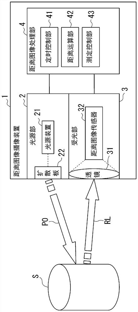
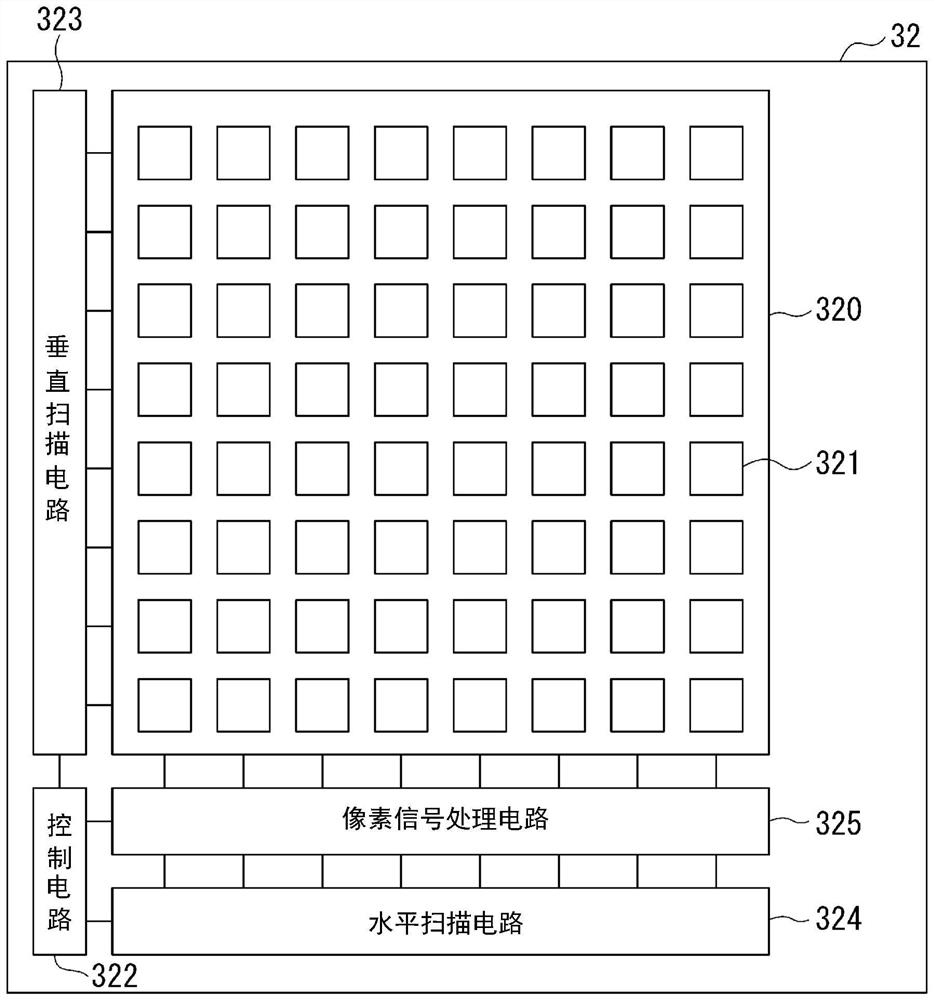
[0050] figure 1 It is a block diagram showing a schematic configuration of the distance imaging device according to the first embodiment of the present invention. figure 1 The distance image pickup device 1 configured as shown includes a light source unit 2 , a light receiver 3 , and a distance image processing unit 4 . exist figure 1 2 also shows a subject S, which is an object to measure the distance in the distance image pickup device 1 .

[0051] The light source unit 2 irradiates the light pulse PO in the space of the imaging target where the subject S of the distance measurement object in the distance image pickup device 1 exists, based on the control from the distance image processing unit 4 . The light source unit 2 is, for example, a surface-emitting semiconductor laser module such as a Vertical Cavity Surface Emitting Laser (VCSEL: Vertical Cavity Surface Emitting Laser). The light source unit 2 includes a l...

no. 2 Embodiment approach

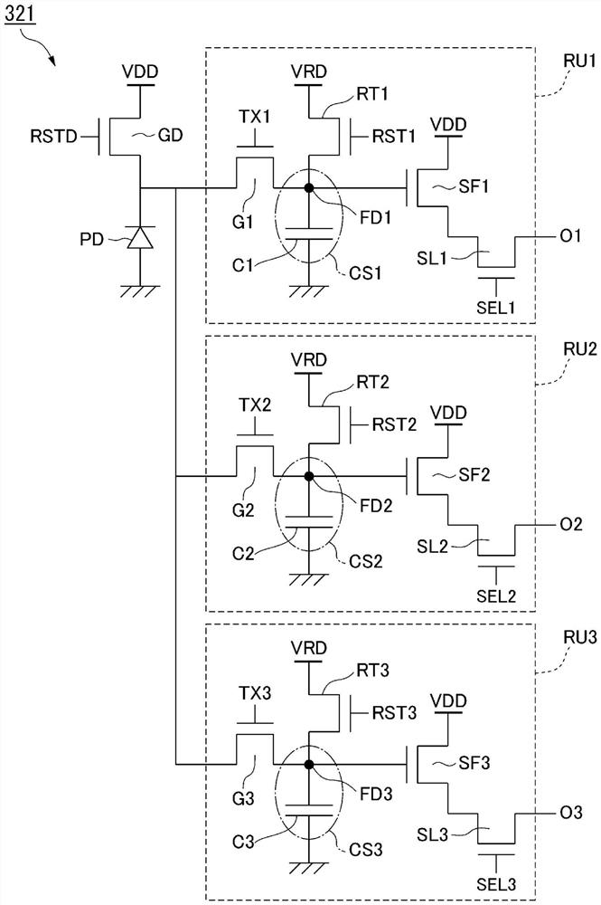
[0217] Next, a second embodiment will be described. This embodiment differs from the above-described embodiments in that the pixel includes four charge storage portions CS1 to CS4.

[0218] Figure 11 It is a timing chart showing the timing of driving the pixel 321 in the second embodiment. about Figure 11 Items such as "Light" in the Figure 12C are the same, so their description is omitted. also, Figure 11 The timing relationship between the irradiation of the light pulse PO, the flare light and the receiving of the reflected light RL is due to the Figure 5A are the same, so their description is omitted.

[0219] Such as Figure 11 As shown, in the present embodiment, the operations corresponding to the intermediate distance mode and the intermediate distance external light mode are performed simultaneously by sequentially bringing the charge storage parts CS1 to CS4 into the conductive state. As a result, the charge amount corresponding to one frame corresponding...


PUM


Abstract

The present invention is provided with: a light source unit that irradiates a measurement space, which is a space to be measured, with light pulses; and a light receiving unit having a pixel provided with a photoelectric conversion element for generating charges corresponding to incident light and a plurality of charge accumulation units for accumulating the charges, and a pixel driving circuit for driving the photoelectric conversion element to generate the charges corresponding to the incident light at a predetermined accumulation timing synchronized with irradiation of the light pulse. A charge storage unit that distributes and stores the charges in each of the pixels; and a distance image processing unit that measures a distance to a subject present in the measurement space on the basis of the amount of charge accumulated by each of the charge accumulation units, the distance image processing unit having a timing control unit that controls the accumulation timing in accordance with a measurement mode. The measurement mode is preset according to the range of the distance to be measured.

Description

technical field [0001] The present invention relates to a distance image pickup device and a distance image pickup method. [0002] This application claims the priority of Japanese Patent Application No. 2019-142536 filed in Japan on August 1, 2019, and uses the contents thereof here. Background technique [0003] Conventionally, there is known a time of flight (Time of Flight, hereinafter referred to as "TOF") distance imaging device, which utilizes the fact that the speed of light is known, and measures the distance between the object and the subject based on the time of flight of light. distance. In the distance imaging device, like the imaging device, a plurality of pixels for detecting light for measuring distance are arranged in a two-dimensional matrix, and the information on the two-dimensional distance from the subject, the subject The image of the body is acquired (captured). [0004] In order to accurately measure the distance to an object existing at a long di...

Claims


Application Information

Patent Timeline
Patent Type & Authority Applications(China)
IPC IPC(8): H04N5/235G01S17/08
CPCG01S17/08H04N23/70G01S17/894G01S7/4865G01S7/4863H04N25/531H04N25/771G01S17/10H04N23/56H04N23/72
Inventor 赤堀知行大久保优畠山邦广高桥聪
Owner 布鲁克曼科技株式会社
Learn More