Structure for side section of vehicle body

A body and structure technology, applied in the field of body side structure, to achieve the effect of simple rigidity and improved rigidity

Inactive Publication Date: 2014-11-12
HONDA MOTOR CO LTD
View PDF7 Cites 0 Cited by
  • Summary
  • Abstract
  • Description
  • Claims
  • Application Information

AI Technical Summary

Problems solved by technology

In this case, considering the structural continuity of the left and right side sills and the left and right rear wheel arches, it is necessary to sufficiently increase the rigidity of the left and right connecting members, so there is room for further improvement.

Method used


Image

  • Structure for side section of vehicle body
  • Structure for side section of vehicle body
  • Structure for side section of vehicle body

Examples


Embodiment 1

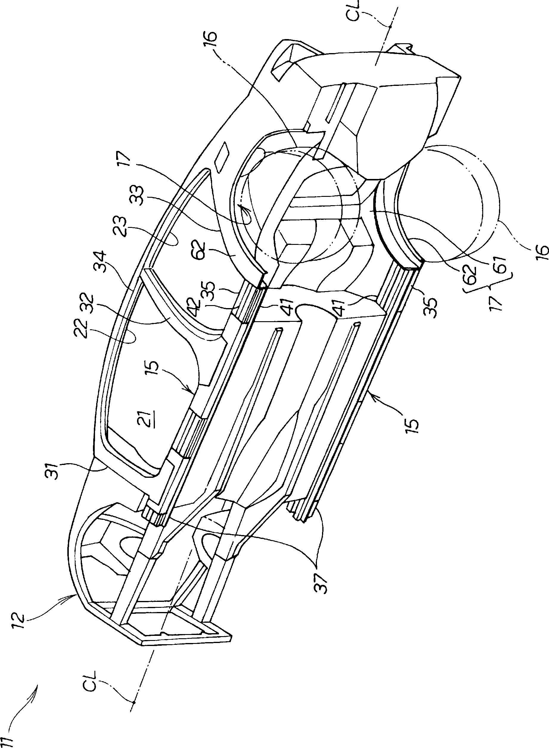
[0043] based on Figure 1 to Figure 8 The vehicle body of Example 1 will be described. Such as figure 1 As shown, the vehicle 11 is a four-door passenger car, and a vehicle cabin 21 is formed inside the central portion of the vehicle body 12 . The vehicle body 12 is constituted by a monocoque body, and is symmetrically formed with respect to a vehicle width centerline CL passing through the center of the vehicle 11 in the vehicle width direction and extending in the vehicle front-rear direction. The vehicle body 12 has a front door opening 22 and a rear door opening 23 on left and right side surfaces, respectively. The front and rear door openings 22 and 23 are opened and closed by unillustrated doors. Further, the vehicle body 12 includes left and right side sills 15 , left and right front pillars 31 , left and right center pillars 32 , left and right rear pillars 33 , left and right roof side rails 34 , and left and right rear wheel arches 17 .

[0044] The left and righ...

Embodiment 2

[0064] based on Figure 9 ~ Figure 13 The vehicle body of Example 2 will be described. The vehicle body 12A of Embodiment 2, except that Figure 1 to Figure 8 The joint member 18 on the left side of the illustrated embodiment 1 is changed to Figure 9 ~ Figure 13 Except for the joint member 18A shown on the left side, it has substantially the same structure as that of the vehicle body 12 of the first embodiment, and description thereof will be omitted. In addition, since the right joining member (not shown) has the same structure as 18 A of left joining members, description is abbreviate|omitted.

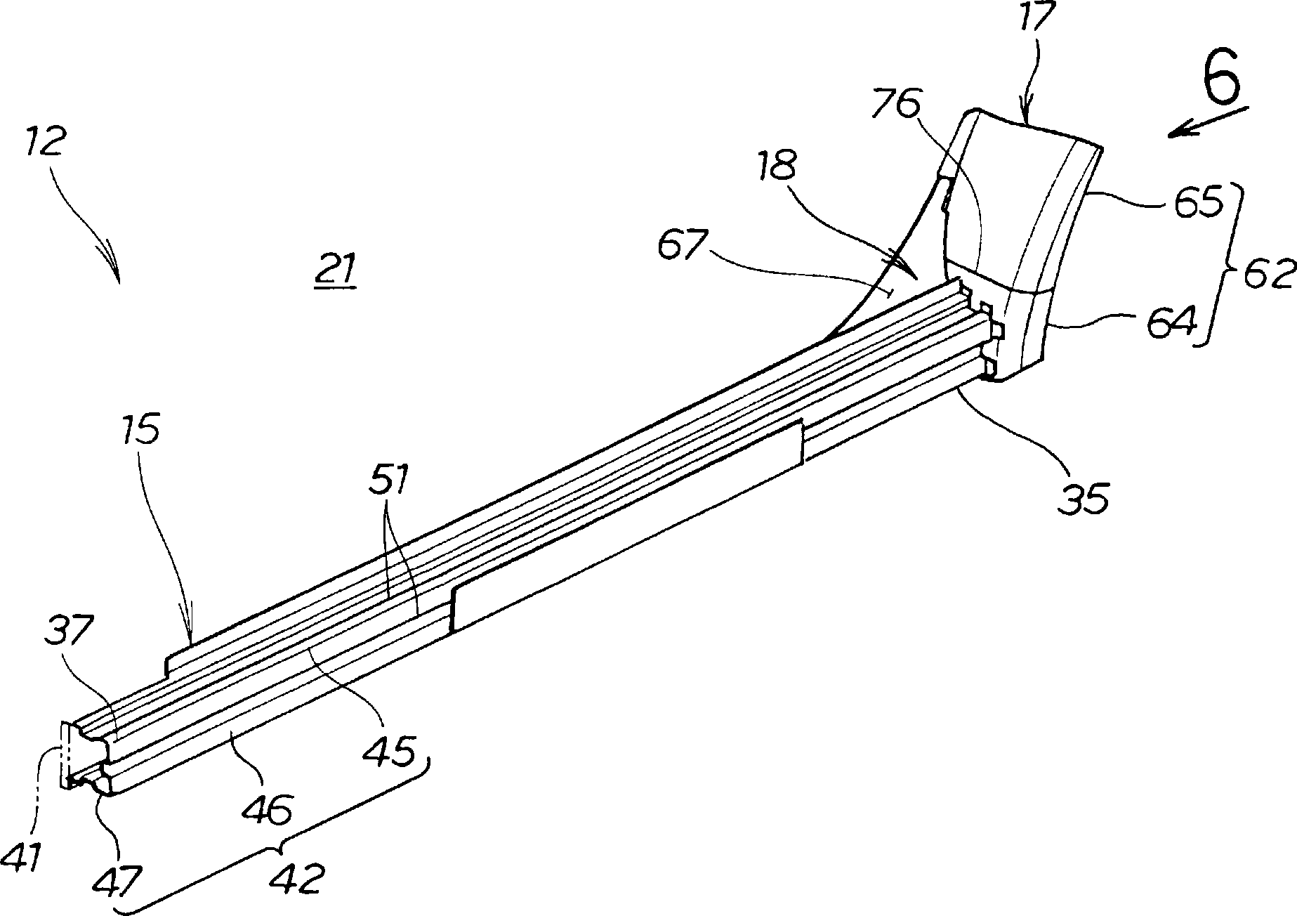
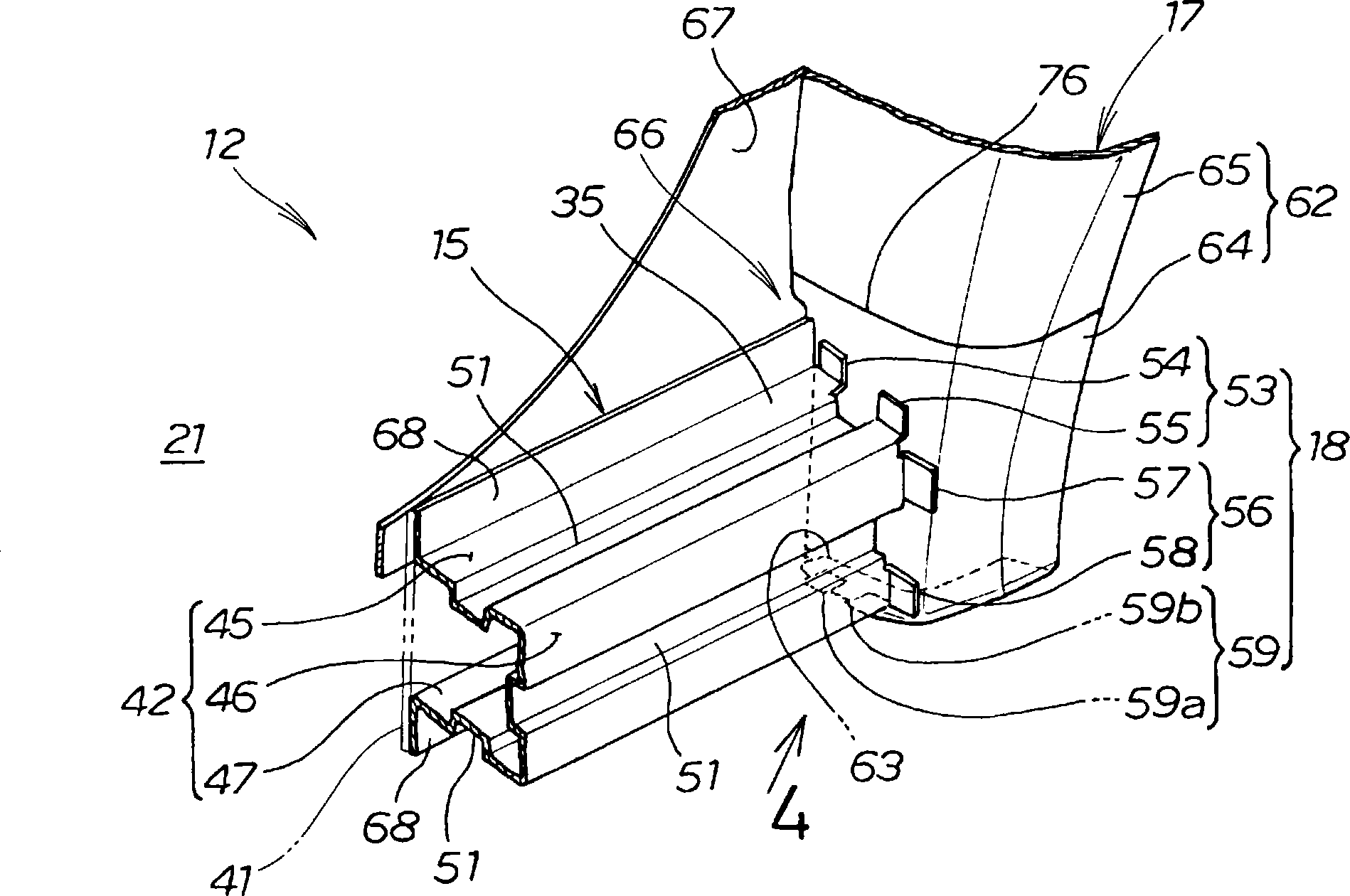
[0065] Such as Figure 9 ~ Figure 12 As shown, the left joining member 18A of the second embodiment is constituted by a separate member from the left side sill 15 . The left joining member 18A is overlapped and joined to the rear end portion 35 of the left side sill outer member 42 , that is, the outer peripheral surface of the rear end portion of the left side sill outer member...

Embodiment 3

[0076] based on Figure 14 as well as Figure 15 The vehicle body of Example 3 will be described. The vehicle body 12B of embodiment 3, except will Figure 9 ~ Figure 13 The joint member 18A on the left side of the illustrated embodiment 2 is changed to Figure 14 as well as Figure 15 Except for the joint member 18B on the left side shown, it has substantially the same structure as the vehicle body 12A of the second embodiment, and description thereof will be omitted. In addition, since the right joining member (not shown) has the same structure as the left joining member 18B, description is abbreviate|omitted.

[0077] Such as Figure 14 as well as Figure 15 As shown, the left joining member 18B of the third embodiment is constituted by a separate member from the left side sill 15 . The left joining member 18B is overlapped and joined to the rear end portion 35 of the left side sill outer member 42 , that is, on the inner surface of the rear end portion of the left s...


PUM


Abstract

A vehicle body (12; 12A; 12B) including: left and right side sills (15, 15) extending in the front-rear direction of the vehicle (11); and rear wheel wells (17, 17) located behind the left and right side sills and covering the left and right rear wheels (16, 16). The left and right side sills are formed in a closed cross-sectional shape continuous from the front ends to the rear ends thereof. The rear end sections (35, 35) of the left and right side sills are joined, with the closed cross-sectional shape maintained, to the left and right rear wheel wells by joining members (18, 18; 18A, 18A; 18B, 18B).

Description

technical field [0001] The present invention relates to a vehicle body side structure in which lower portions of left and right rear wheel arches are joined to rear end portions of left and right side sills extending in the front-rear direction of the vehicle body located on the left and right sides of the vehicle body. Background technique [0002] It is known from Patent Document 1 that the left and right side sills are one of the main components constituting the frame of the vehicle body. In the vehicle body known from Patent Document 1, the side sill is reinforced by reinforcing members. The reinforcing member is provided along the longitudinal direction of the side sill and inside. In the case of a side collision of the vehicle, the reinforcement member can suppress bending deformation of the side sill due to the collision force acting on the side of the vehicle. [0003] In recent years, techniques for further improving the rigidity of the vehicle body have been soug...

Claims


Application Information

Patent Timeline
Patent Type & Authority Patents(China)
IPC IPC(8): B62D25/20
CPCB62D25/16B62D25/025
Inventor 田村尚之高桥康一
Owner HONDA MOTOR CO LTD
Why Eureka
Try Eureka