Composite component

A technology for composite parts and structural parts, applied in the direction of vehicle parts, superstructure, superstructure sub-assembly, etc., can solve the problem of reducing the strength of composite parts, and achieve the effect of preventing corrosion, high hardness and strength, and improving protection ability

Inactive Publication Date: 2012-10-17
HENKEL KGAA
View PDF10 Cites 11 Cited by
  • Summary
  • Abstract
  • Description
  • Claims
  • Application Information

AI Technical Summary

Problems solved by technology

However, this material saving may result in a reduction in the strength of the composite part

Method used


Image

  • Composite component
  • Composite component
  • Composite component

Examples


Embodiment Construction

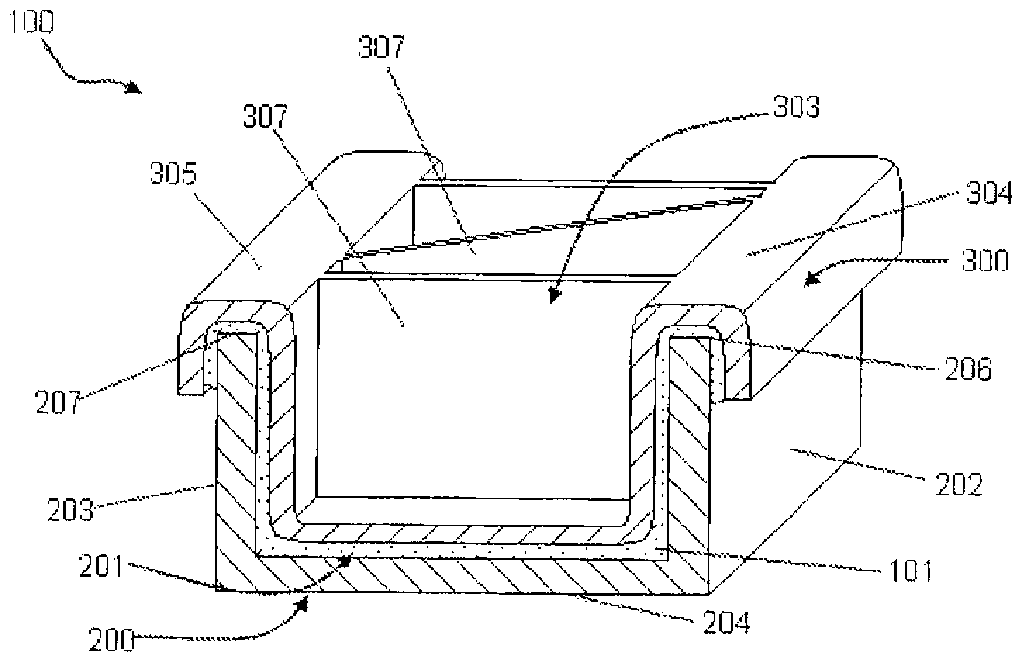
[0077] figure 1 A composite component 100 is shown having a channel shell 100 and a likewise channel-shaped structural component 300 placed in the channel shell 200 . In the shown sectional view, the case 200 has a U-shaped profile and includes a bottom 204 partially enclosing a space 201 , a first wall 202 and a second wall 203 . The structural part 300 arranged in the space 201 is arranged at a distance from the bottom 204 and from the walls 202 , 203 . A gap filled with the structural material 101 is provided between the structural member 300 and the case 200 . In the case of the present invention, this is a thermally expandable structural material 101 which, in the exemplary embodiment shown, is in an expanded state and which, on the one hand, provides for the fixation of the structural part 300 on the shell 200 and, on the other hand, in particular with The gap between the structural member 300 and the case 200 is filled in such a way that dirt and moisture cannot enter...


PUM


Abstract

The invention relates to a composite component (100) comprising a shell (200) that surrounds at least some areas of a chamber (201) and comprising a structural component (300) for reinforcing the shell (200). The structural component (300) is spaced from a wall (202, 203, 204) of the shell (200) at least in some areas, said wall determining the chamber (201), and a structural material (101) is provided at least along some areas between the wall (202, 203, 204) of the shell (200) and the structural component (300). The shell (200) has at least one free edge (206, 207), and the structural component (300) extends over at least some areas of the free edge (206, 207) of the shell (200).

Description

technical field [0001] The invention relates to a composite component composed of a shell at least partially peripherally delimiting a space, and to a structural component having a structural material arranged at least partially between the shell and the structural component. Background technique [0002] Composite components of this type are particularly suitable for use in the vehicle sector. Utilized shells are, for example, sill beams, A-pillars, B-pillars or C-pillars, cross-links, steering knuckles, or another at least partially channel-shaped or shell-shaped structure reinforced in particular by means of structural components and structural materials. part. [0003] A component of the kind described above is disclosed in DE 69533457 T2: a composite component comprising: an outer structural part configured as a C-shaped rail with an outer wall surface and an inner wall surface; parts are identical and have the shape of an outer wall surface and an inner wall surface,...

Claims


Application Information

Patent Timeline
Patent Type & Authority Applications(China)
IPC IPC(8): B62D29/00
CPCB60G7/001B62D29/005B62D29/001B60G2206/122B62D29/004B60G2206/7101B60G2206/70Y10T428/13Y10T428/239Y10T428/2419Y10T428/24752B62D25/02B62D29/00
Inventor K·韦施J·席琳
Owner HENKEL KGAA
Why Eureka
Try Eureka