
Slag discharge condition monitoring apparatus and method for monitoring slag discharge condition

A monitoring device and status technology, which is applied in the direction of combustion methods, granular/powdered fuel gasification, incinerators, etc., can solve the problems of reduced measurement accuracy, inability to fully monitor the status and changes of slag discharge, and prevent the reduction of measurement accuracy Effect

Inactive Publication Date: 2012-10-17
MITSUBISHI HEAVY IND LTD
View PDF5 Cites 0 Cited by
  • Summary
  • Abstract
  • Description
  • Claims
  • Application Information

AI Technical Summary

Problems solved by technology

[0005] Compared with the monitoring method using the underwater microphone, the monitoring method using the video camera has the problem that the view around the slag mouth is poor, and the discharge status of the slag cannot be fully monitored, or the molten slag is also cooled and solidified by the air cooling the video camera. The problem that it is easy to hinder the discharge of slag
[0006] On the other hand, in the monitoring method using the underwater microphone described in Patent Document 1, since the installation position of the underwater microphone is not specified relative to the position of the slag discharge gap, the underwater microphone has become more and more difficult to use as the size of the coal gasification equipment increases. When the relationship with the above-mentioned water impact position changes due to the operating conditions, there is a problem that the level of sound in the water measured by the underwater microphone changes, and there is a possibility that the measurement accuracy of the slag discharge condition will decrease.

Method used


Image

  • Slag discharge condition monitoring apparatus and method for monitoring slag discharge condition
  • Slag discharge condition monitoring apparatus and method for monitoring slag discharge condition
  • Slag discharge condition monitoring apparatus and method for monitoring slag discharge condition

Examples


no. 1 approach

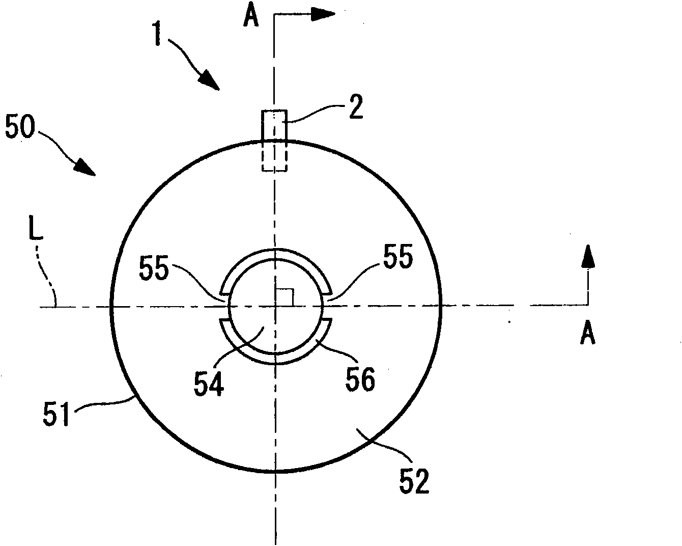
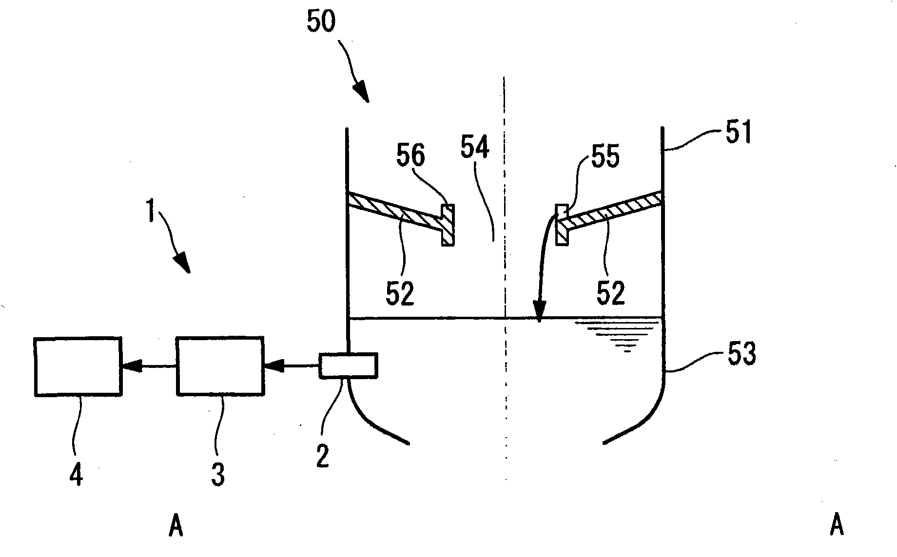
[0052] Below, refer to figure 1 and figure 2 A slag discharge status monitoring device according to a first embodiment of the present invention will be described.

[0053] figure 1 It is a top view explaining the structure of the slag discharge state monitoring apparatus of this embodiment. figure 2 is description figure 1 The A-A cross-sectional view of the outline of the slag discharge status monitoring device.

[0054] like figure 1 and figure 2 As shown, the slag discharge status monitoring device 1 of this embodiment is installed in a combustion furnace (furnace facility) 50 of a coal gasification furnace of a coal gasification facility, and monitors the discharge status of molten slag generated in the combustion furnace 50. , or an alarm is issued when it falls intermittently.

[0055] The combustion furnace 50 is provided with: a combustion furnace main body (furnace) 51 that burns pulverized coal or charcoal inside, a furnace bottom 52 where the burned coal a...

no. 2 approach

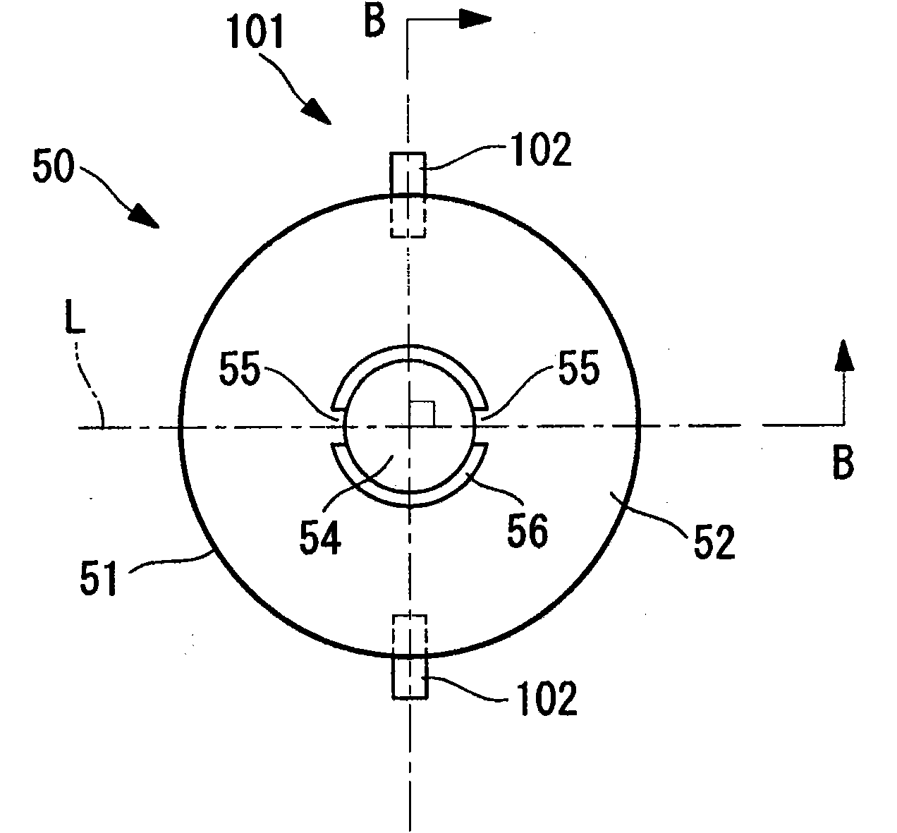
[0083] Below, refer to image 3 and Figure 4 A second embodiment of the present invention will be described.

[0084] The basic configuration of the slag discharge status monitoring device of this embodiment is the same as that of the first embodiment, but the arrangement of the underwater sound detector is different from that of the first embodiment. Therefore, in this embodiment, only the image 3 and Figure 4 The arrangement of the underwater sounder will be described, and the description of other constituent elements and the like will be omitted.

[0085] image 3 It is a top view explaining the structure of the slag discharge state monitoring apparatus of this embodiment. Figure 4 is description image 3 The B-B cross-sectional view of the outline of the slag discharge status monitoring device.

[0086] In addition, the same code|symbol is attached|subjected to the same component as 1st Embodiment, and the description is abbreviate|omitted.

[0087] like imag...

no. 3 approach

[0097] Below, refer to Figure 5 and Image 6 A third embodiment of the present invention will be described.

[0098] The basic configuration of the slag discharge status monitoring device of this embodiment is the same as that of the first embodiment, but the arrangement of the underwater sound detector is different from that of the first embodiment. Therefore, in this embodiment, using Figure 5 and Image 6 Only the arrangement of the underwater sound detector will be described, and the description of other components and the like will be omitted.

[0099] Figure 5 It is a top view explaining the structure of the slag discharge state monitoring apparatus of this embodiment. Image 6 is description Figure 5 The C-C cross-sectional view of the outline of the slag discharge status monitoring device.

[0100] In addition, the same code|symbol is attached|subjected to the same component as 1st Embodiment, and the description is abbreviate|omitted.

[0101] like Figur...


PUM


Abstract

A slag discharge condition monitoring apparatus and a method for monitoring a slag discharge condition that are capable of preventing the detection accuracy of the slag discharge condition from being lowered due to scaling-up of a coal gasification facility, especially a coal gasification furnace, are provided. A slag discharge condition monitoring apparatus (1) is arranged in a furnace facility (50) that processes molten slag produced within a furnace (51) by dripping the molten slag from a slag hole (54) provided on a furnace bottom (52) into cooling water outside the furnace. The slag discharge condition monitoring apparatus is characterized in that in the cooling water, an underwater microphone (2) is disposed at distances approximately equal from a pair of slag taps (55, 55) that are disposed opposite to each other and that cause the molten slag to flow into the slag hole (54).

Description

technical field [0001] The present invention relates to a slag discharge state monitoring device and a slag discharge state monitoring method used in commercial or industrial coal gasification facilities. Background technique [0002] In the conventional coal gasification equipment, the burned coal ash stays as molten slag at the bottom of the combustion furnace, flows out from the slag opening of the slag outlet, and falls into the slag hopper arranged at the lower part. Cooling water is stored inside the slag hopper, and the molten slag is cooled and solidified by the cooling water, and then discharged out of the system. [0003] The slag discharge status monitoring device used in coal gasification equipment is used to monitor the drop status of molten slag to the slag hopper. The following related technologies have been proposed so far. That is, the technology of monitoring the drop status of molten slag by using a video camera for monitoring, or by using An underwater m...

Claims


Application Information

Patent Timeline
Patent Type & Authority Applications(China)
IPC IPC(8): F23J1/00C10J3/52
CPCC10J2300/093F23J2900/01002Y02E20/18F23G2207/10C10J2300/0956C10J3/526F23G2900/55005C10J2300/1846C10J3/72C10J3/466F23N5/16F23J1/00
Inventor 菅沼直树山田哲也田口睦明
Owner MITSUBISHI HEAVY IND LTD
Learn More