Optical body, method for manufacturing same, window member, sliding window, and sunlight blocking device

A technology of optical body and optical layer, applied in the field of optical body, can solve problems such as glare and reflection, and achieve the effect of suppressing glare and reflection

Inactive Publication Date: 2012-10-17
DEXERIALS CORP
View PDF17 Cites 20 Cited by
  • Summary
  • Abstract
  • Description
  • Claims
  • Application Information

AI Technical Summary

Problems solved by technology

Therefore, the problem of glare or reflection

Method used


Image

  • Optical body, method for manufacturing same, window member, sliding window, and sunlight blocking device
  • Optical body, method for manufacturing same, window member, sliding window, and sunlight blocking device
  • Optical body, method for manufacturing same, window member, sliding window, and sunlight blocking device

Examples


no. 3 approach ( 100

[0085] 3. Third embodiment (an example of a louver-type transflective layer)

[0086] 4. Fourth embodiment (example in which a light scatterer is provided in an optical film)

[0087] 5. Fifth embodiment (in which an example of a self-cleaning layer is provided)

[0088] 6. Sixth embodiment (an example in which the optical film is applied to a blind device)

[0089] 7. Seventh embodiment (an example in which the optical film is applied to a rolling screen device)

[0090] 8. Eighth embodiment (in which the optical film is applied to a construction example)

no. 1 approach

[0092] [Structure of optical film]

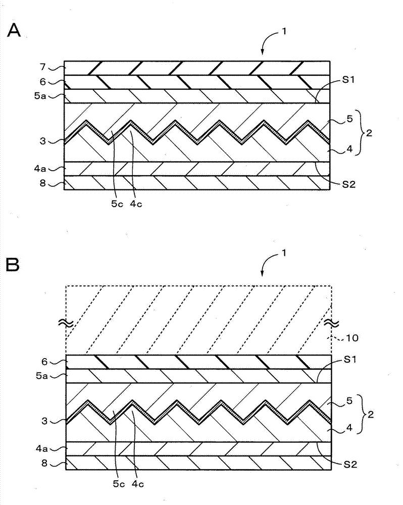
[0093] figure 1 A is a cross-sectional view showing one example of the configuration of the optical film according to the first embodiment of the present invention. figure 1 B is a sectional view showing an example in which the optical film according to the first embodiment of the present invention is attached to an adherend. The optical film 1 as an optical body is an optical film having so-called directional reflection performance. Such as figure 1 As shown in A, the optical film 1 includes an optical layer 2 having a concavo-convex interface therein, and a transflective layer 3 provided on the interface of the optical layer 2 . The optical layer 2 includes a first optical layer 4 having a first surface of a concavo-convex shape and a second optical layer 5 having a second surface of a concavo-convex shape. The interface in the optical layer is formed by a first surface and a second surface each having a concavo-convex shape and being...

no. 2 approach

[0184] Figures 13 to 16 An example of the configuration of the structure formed in the optical film according to the second embodiment of the present invention is shown. Parts in the second embodiment corresponding to parts in the first embodiment are indicated by the same reference numerals. The second embodiment differs from the first embodiment in that structures 4 c are two-dimensionally arranged on the main surface of the first optical layer 4 . Preferably, the two-dimensional arrangement represents the two-dimensional arrangement in the most densely packed state. This is because such an arrangement can improve directional reflectivity.

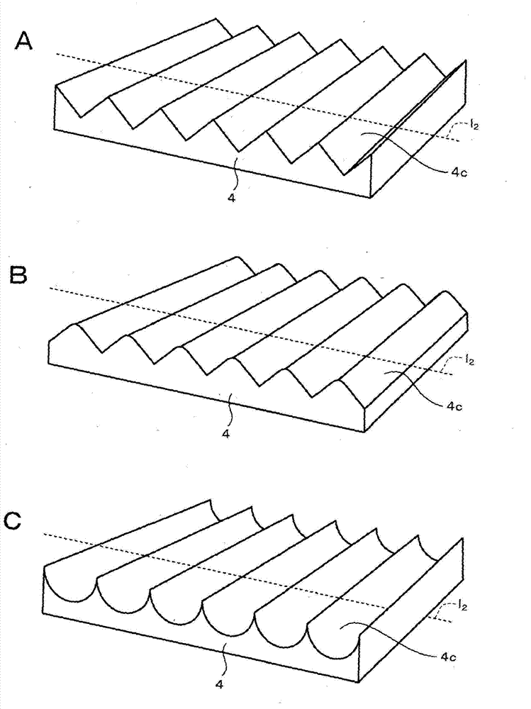
[0185] Such as Figure 13 As shown in A to 13C, for example, cylindrical structures (cylinders) 4 c are arranged perpendicularly to each other on the principal surface of the first optical layer 4 . Specifically, the first structures 4c aligned in the first direction and the second structures 4c aligned in the second direction perpe...


PUM

PropertyMeasurementUnit
surface roughnessaaaaaaaaaa
storage modulusaaaaaaaaaa

Abstract

Disclosed is an optical body capable of minimizing glare and reflection and blocking sunlight including the visible light. The optical body is provided with a semitransparent layer formed on a projection / recess surface and a second optical layer formed over the projection / recess surface on which the semitransparent layer is formed so as to cover the projection / recess surface. The semitransparent layer directively reflects part of the light incident on the incidence surface at an incidence angle (?, f) in a direction other than the direction of the angle of regular reflection (-?, f+180 DEG ) (where ? is an angle formed by a perpendicular (l1) perpendicular to the incidence surface and the incident light incident on the incidence surface or the reflected light allowed to exit from the incidence surface, f is the angle formed by a specific line (l2) in the incidence surface and the component of the incident light or the reflected light projected on the incidence surface, the specific line (l2) in the incidence surface is the axis such that the intensity of reflection in the f direction becomes maximum when the incident angle (?, f) is fixed and when the semitransparent layer is rotated around the perpendicular (l1) perpendicular to the incidence surface).

Description

technical field [0001] The present invention relates to an optical body, a method for manufacturing the same, a window member, a fitting (fitting), and a solar shading device. In particular, the invention relates to an optical body capable of blocking sunlight. Background technique [0002] Recently, films or panels for windows to block sunlight are used from the viewpoint of reducing air-conditioning loads. In particular, films or panels are used that block both visible rays as well as infrared light, since more than half of the sun's energy is visible rays. Furthermore, partial blocking of visible light rays is also important for the purpose of reducing glare caused by the afternoon sun. [0003] A transflective layer (transflective layer) made of a metal obtained by film deposition is known as such a film or panel (for example, see Patent Documents 1 to 3). However, since the transflective layer is deposited on the flat plates in these films or panels, visible light ra...

Claims


Application Information

Patent Timeline
Patent Type & Authority Applications(China)
IPC IPC(8): G02B5/08B32B3/30B32B7/02E06B3/70G02B1/10G02B5/22
CPCE06B9/386B32B7/02G02B5/22G02B5/08B32B2307/412B32B2307/71B32B2307/416B32B3/30G02B5/045G02B1/10E06B2009/2417B32B2551/00B32B2419/00G02B1/118G02B5/208
Inventor 长浜勉铃木真树竹中博也榎本正
Owner DEXERIALS CORP
Why Eureka
Try Eureka