Vacuum rake dryer

A rake dryer and vacuum technology, which is applied in the direction of drying solid materials, drying, lighting and heating equipment, etc., can solve the problems of uneven mixing and unsatisfactory drying, and achieve uniform mixing, ideal drying effect and wide range Effect

Inactive Publication Date: 2012-10-24
金伟均
View PDF0 Cites 1 Cited by
  • Summary
  • Abstract
  • Description
  • Claims
  • Application Information

AI Technical Summary

Problems solved by technology

[0004] The technical problem to be solved by the present invention is: solve the technical problem of uneven stirring and unsatisfactory drying in the existing vacuum rake dryer

Method used


Image

  • Vacuum rake dryer

Examples


Embodiment Construction

[0011] The present invention is described in further detail now in conjunction with accompanying drawing. These drawings are all simplified schematic diagrams, which only illustrate the basic structure of the present invention in a schematic manner, so they only show the configurations related to the present invention.

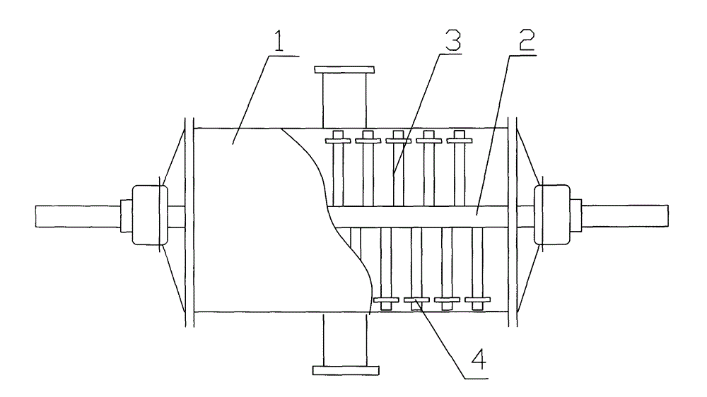
[0012] Such as figure 1 The specific embodiment of the vacuum rake dryer shown in the present invention includes a drying cylinder 1, an agitator is arranged in the drying cylinder 1, and the agitator includes a mounting shaft 2 and a stirring rod 3 arranged on the mounting shaft 2, In order to make the stirring more uniform, the end of the stirring rod 3 is provided with a short rod 4 perpendicular to the stirring rod 3, and the stirring rod 3 is arranged on the installation shaft 2 in a staggered cross shape. Helically set on the mounting shaft 2.

[0013] In this vacuum rake dryer, the end of the stirring rod 3 is provided with a short rod 4, so that the ...


PUM


Abstract

The invention relates to a vacuum rake dryer which comprises a drying cylinder. A stirrer is arranged in the drying cylinder, the stirrer comprises an installation shaft and a stirring rod arranged on the installation shaft, a short rod vertical to the stirring rod is arranged at one end of the stirring rod, and the stirring rod is arranged on the installation shaft in staggered and crossed modes. The vacuum rake dryer is wide in stirring scope, even in stirring and ideal in stirring effect.

Description

technical field [0001] The invention relates to a vacuum rake dryer. Background technique [0002] Vacuum rake dryers are mostly used in the chemical, feed, and food industries to dry pellets and powders. It is a novel horizontal intermittent vacuum drying equipment. The wet material is evaporated by conduction, and the agitator moves in the dryer to form a circulating flow. After the water evaporates, it is drawn out by the vacuum pump, thus achieving the drying effect. [0003] When the existing vacuum rake dryer is drying, the material between the stirring rod and the stirring rod cannot be well stirred, so the stirring of the wet material is not very uniform, which leads to slow drying speed and unsatisfactory drying effect . Contents of the invention [0004] The technical problem to be solved by the present invention is to solve the technical problems of non-uniform stirring and unsatisfactory drying in the existing vacuum rake dryer. The invention provides a vacu...

Claims


Application Information

Patent Timeline
Patent Type & Authority Applications(China)
IPC IPC(8): F26B25/04
Inventor 金伟均
Owner 金伟均
Why Eureka
Try Eureka