
sand mixer for foundry

A technology of sand mixer and cylinder, which is applied in the direction of casting molding equipment, cleaning/processing machinery of casting mold materials, manufacturing tools, etc. It can solve the problems that the mixing effect needs to be strengthened and does not move, so as to achieve the effect of rolling and mixing Good, uniform rolling effect, good mixing effect

Active Publication Date: 2020-09-01
杭州兴海铸造有限公司
View PDF9 Cites 0 Cited by
  • Summary
  • Abstract
  • Description
  • Claims
  • Application Information

AI Technical Summary

Problems solved by technology

[0004] When the above-mentioned sand mixer is used to mix the molding sand, although the molding sand can be stirred and rolled, the position of the grinding wheel and the middle grinding roller basically does not move, and the same position is rolled and stirred, resulting in an overall mixing effect that needs to be strengthened. needs improvement

Method used


Image

  • sand mixer for foundry
  • sand mixer for foundry
  • sand mixer for foundry

Examples


Embodiment

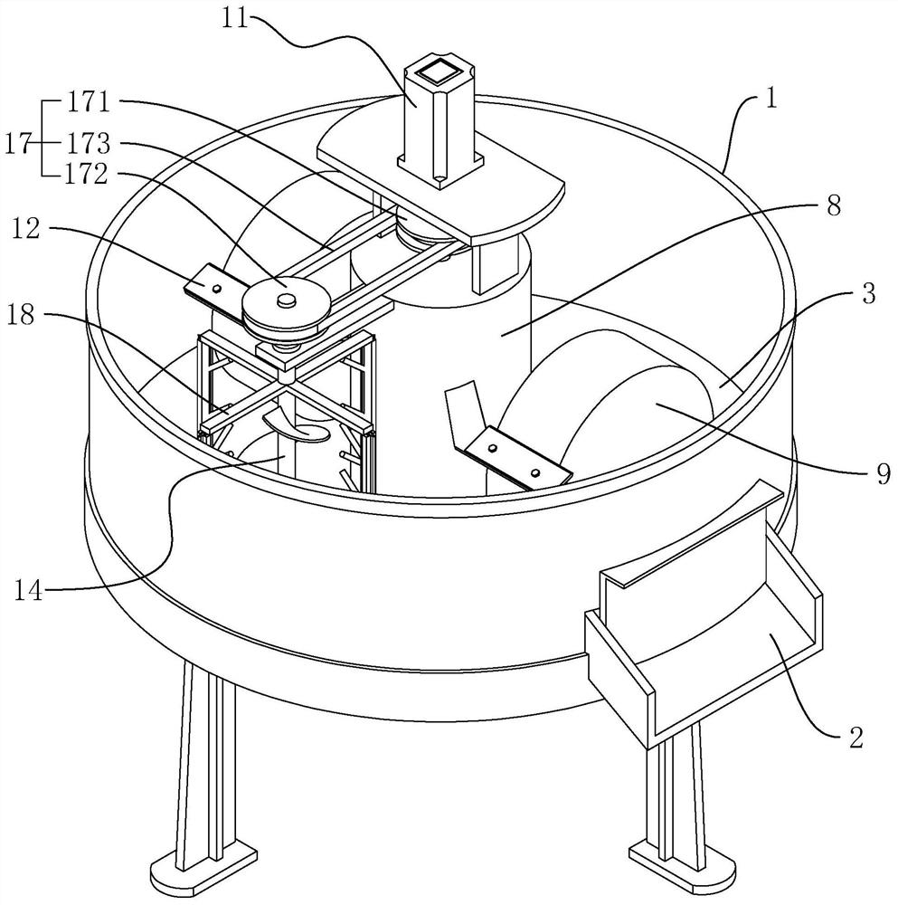
[0039] A sand mixer for foundry, such as figure 1 As shown, it includes a cylindrical cylinder body 1, the outer wall of the cylinder body 1 is provided with a discharge port 2 near the bottom, and a closing plate slides on the discharge port 2, and the closing plate is used to control the opening of the discharge port 2 and closed.

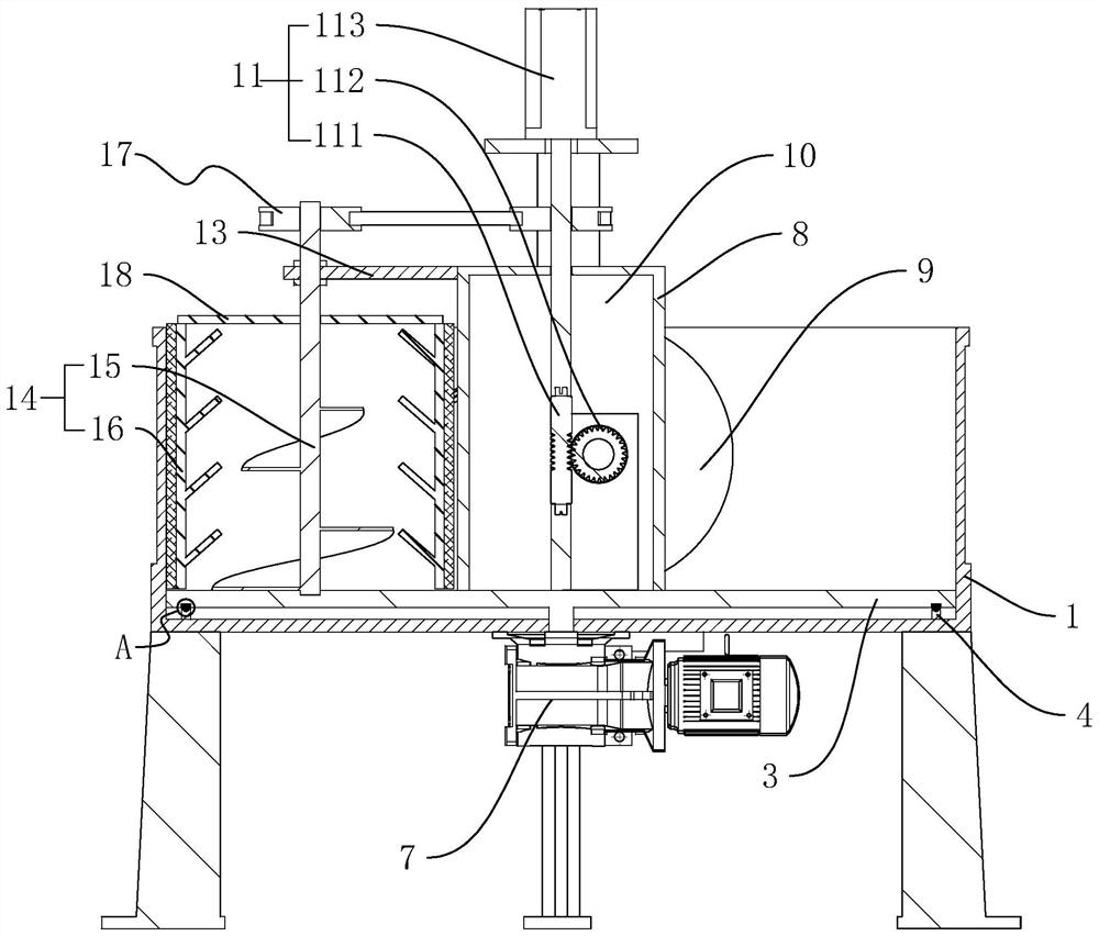
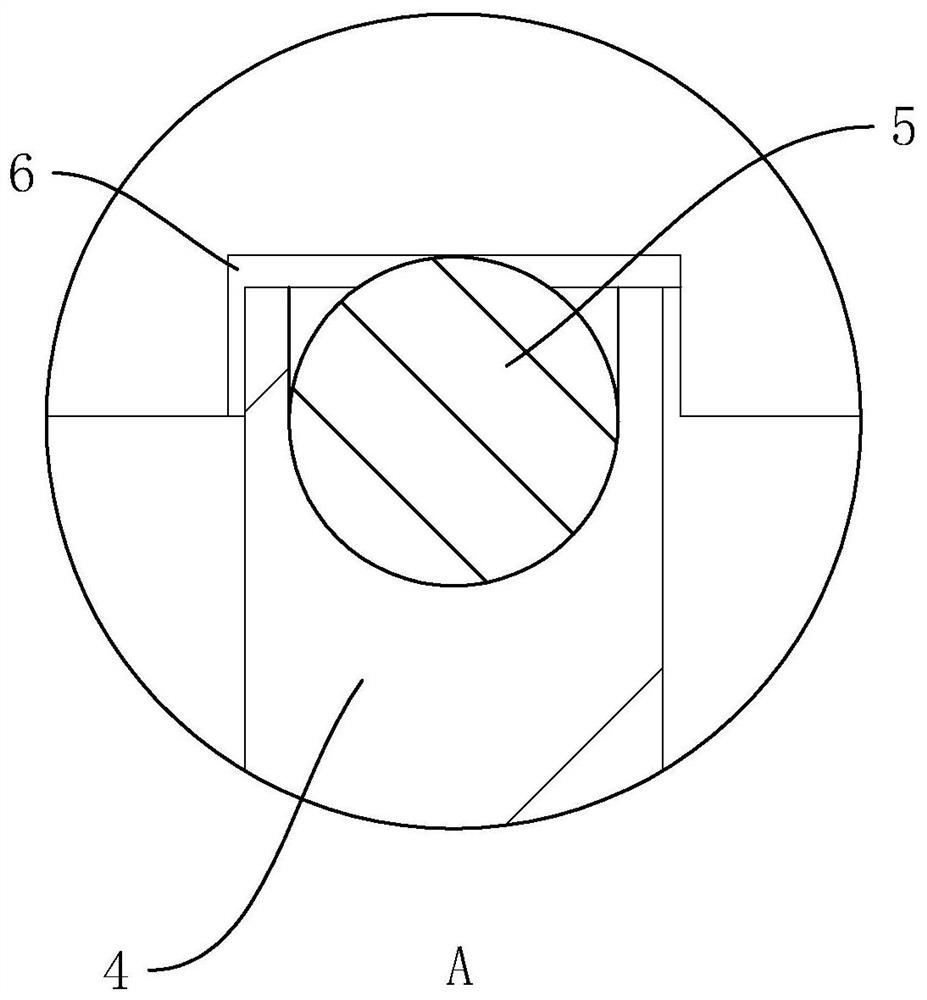
[0040] Such as figure 2 , image 3As shown, a mounting plate 3 is connected to the cylinder body 1 for coaxial rotation, and the mounting plate 3 is arranged near the bottom of the cylinder body 1 . The mounting plate 3 is arranged in a circular plate shape, the axis of the mounting plate 3 coincides with the barrel 1, and the outer wall of the mounting plate 3 is set against the inner wall of the barrel 1, and the inner wall of the bottom of the barrel 1 is provided with a positioning ring 4 for positioning. The upper end surface of the ring 4 is rotatably embedded with a roller 5 . The end face of the mounting plate 3 corresponds to the po...


PUM


Abstract

The invention discloses a sand mixing machine for casting, and relates to the technical field of casting. According to the technical scheme, the sand mixing machine comprises a barrel body and a runner wheel. The interior of the barrel body is coaxially connected with an installation plate. A driving piece is further arranged at the bottom of the barrel body. An installation part is arranged on the upper end face of the installation plate. The runner wheel is correspondingly and rotationally connected to the installation part. A driving assembly is further arranged on the installation part andcomprises a worm rotationally connected with the interior of the installation part, a worm wheel fixedly connected to the runner wheel and a driving motor. An extending plate is fixed to the installation part in the radial direction of the barrel body. A stirring assembly is further arranged in the barrel body and correspondingly connected with the extending plate. The stirring assembly comprisesa main stirring piece and an auxiliary stirring piece. The worm is provided with a transmission assembly capable of driving a main stirring shaft to rotate. By means of rotation of the installation plate, the runner wheel on the installation plate and the stirring assembly can rotate along the axis of the barrel body in the grinding and stirring process, thus, the grinding and stirring range is larger, and therefore, the overall grinding and mixing effect is better.

Description

technical field [0001] The invention relates to the technical field of foundry, more specifically, it relates to a sand mixer for foundry. Background technique [0002] The sand mixer is a device that uniformly mixes the components in the molding sand and effectively coats the binder on the surface of the sand grains. In the foundry field, a sand mixer is a casting equipment used for mixing molding sand or core sand. The old sand, new sand, molding sand binder and auxiliary materials are mixed evenly through the sand mixer. [0003] For example, the Chinese utility model patent whose patent number is CN206335089U discloses a sand mixer capable of improving sand mixing efficiency. The bottom is provided with a rotating drive device that drives the rotating shaft to rotate; the rotating shaft is provided with two rolling wheels; the bottom of the inner cavity of the cylinder is provided with an intermediate grinding roller, and the intermediate grinding roller is located betw...

Claims


Application Information

Patent Timeline
Patent Type & Authority Patents(China)
IPC IPC(8): B22C5/04
CPCB22C5/04B22C5/044
Inventor 李金海
Owner 杭州兴海铸造有限公司
Learn More