
Infrared touch screen employing lens

An infrared touch and light distribution mirror technology, applied in the input/output process of data processing, instruments, calculations, etc., can solve the problems of large frame size, high cost, heavy infrared touch display device, etc., and reduce the width , to achieve the effect of the border

Active Publication Date: 2012-10-24
SHENZHEN TIMELINK ECHNOLOGY CO LTD
View PDF8 Cites 6 Cited by
  • Summary
  • Abstract
  • Description
  • Claims
  • Application Information

AI Technical Summary

Problems solved by technology

[0003] The disadvantage of the infrared touch screen with the above structure is: since the printed circuit board used to connect the infrared emitting tube and the infrared receiving tube is embedded around the flat display part, and the printed circuit board and the flat display part are arranged on the same plane, When encapsulating the outer frame of the flat panel display component, the outer frame needs to package the printed circuit board, so the size of the outer frame of the flat panel display component is correspondingly larger, so that the infrared touch display The device is very thick and heavy, resulting in a large volume and high cost of the entire infrared touch screen
As a result, it is difficult to use infrared touch technology on many ultra-thin and ultra-narrow displays

Method used


Image

  • Infrared touch screen employing lens
  • Infrared touch screen employing lens

Examples


Embodiment Construction

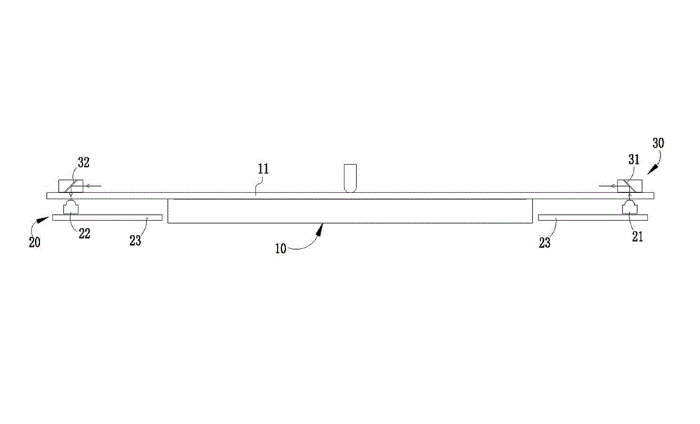
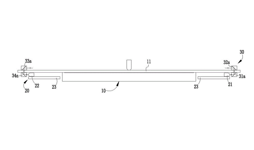
[0016] The following will be combined with Figures 1 to 2 As well as the preferred embodiments, an infrared touch screen using a light distribution mirror proposed by the present invention will be described in more detail.

[0017] The present invention provides an infrared touch screen using a light distribution mirror, which includes a liquid crystal display 10 and an infrared transceiver module 20, wherein the infrared transceiver module 20 includes an infrared emitting array 21 composed of several infrared emitting tubes, composed of An infrared receiving array 22 and a printed circuit board 23 composed of several infrared receiving tubes, the infrared emitting array 21 and the infrared receiving array 22 are all welded on the printed circuit board 23, and it is characterized in that: the infrared emitting array 21 and the infrared receiving array Receiving array 22 is all positioned at the rear side of the display surface of described liquid crystal display 10, is provid...


PUM


Abstract

An infrared touch screen employing a lens comprises a liquid crystal display and an infrared transceiver module, wherein the infrared transceiver module comprises an infrared emission array composed of a plurality of infrared emission tubes, an infrared receiving array composed of a plurality of infrared receiving tubes and a printed circuit board; the infrared emission array and the infrared receiving array are both welded on the printed circuit board; the infrared emission array and the infrared receiving array are both located at the rear side of the display surface of the liquid crystal display; an optical assembly is arranged between the emission end of the infrared emission array and the receiving end of the infrared receiving array so that the infrared ray emitted by the infrared emission array forms an infrared ray detection network in parallel to the display surface at the front side of the liquid crystal display when the infrared ray is transferred to the infrared receiving array; the optical assembly is arranged at the periphery of the liquid crystal display; and one end of the optical assembly for distributing and emitting the infrared ray detection network is located at the front side of the display surface of the liquid crystal display.

Description

technical field [0001] The invention relates to the field of display and touch control, in particular to an infrared-sensing touch-control display device using a light distribution mirror. Background technique [0002] As far as touch screens currently appearing on the market are concerned, infrared touch screens occupy a certain share. For example, the two patented products disclosed in Patent No. 200720052423.3 and Patent No. 200720051069.2 are common infrared touch display devices, which mainly include flat panel display components ( Including liquid crystal display), four printed circuit boards with infrared emitting tubes and infrared receiving tubes welded around the flat panel display components, and an outer frame, wherein the infrared emitting tubes and infrared receiving tubes are arranged on the flat panel display The display front side of the component, and the infrared emitting tube and the infrared receiving tube are respectively arranged on the left and right ...

Claims


Application Information

Patent Timeline
Patent Type & Authority Applications(China)
IPC IPC(8): G06F3/042
CPCG06F3/042G06F3/0421
Inventor 陈伟山
Owner SHENZHEN TIMELINK ECHNOLOGY CO LTD
Learn More