Drainage armour clamp of high voltage alternative current circuit tension resisting tower

A high-voltage AC and tension tower technology, applied in the direction of mechanical vibration damping device, etc., can solve the problems of increasing cost, increasing the dead weight of the drainage line, and discharging the drainage line, so as to reduce the project cost, shorten the length of the cross arm, and prevent the wind flash. Effect

Active Publication Date: 2015-04-15
STATE NUCLEAR ELECTRIC POWER PLANNING DESIGN & RES INST CO LTD
View PDF4 Cites 0 Cited by
  • Summary
  • Abstract
  • Description
  • Claims
  • Application Information

AI Technical Summary

Problems solved by technology

The disadvantage is that the counterweight that can be increased by jumping strings is limited, so the windage angle of the drainage line can only be appropriately reduced
[0008] The hard jumper drainage method is to add a hard jumper device to the drainage line to further increase the weight of the drainage line and better control the wind angle of the drainage line. However, the cost increases more than the previous two methods, and when the actual When the wind speed exceeds the design condition, the diversion line may still discharge the tower and cause the line to trip
[0009] Since the design wind speed of the transmission line is the average maximum wind speed within 10 minutes once every 30 years, it is a statistical data. If an instantaneous strong wind occurs in a small area using the above method, it may still cause the discharge line to discharge to the tower, causing the transmission line to trip. , which is also the most important part of the above-mentioned drainage method. Although the design of the tower head of the strain tower meets the design conditions of the wind speed once in 30 years, flashover in high winds still occurs during operation.

Method used


Image

  • Drainage armour clamp of high voltage alternative current circuit tension resisting tower
  • Drainage armour clamp of high voltage alternative current circuit tension resisting tower
  • Drainage armour clamp of high voltage alternative current circuit tension resisting tower

Examples


Embodiment Construction

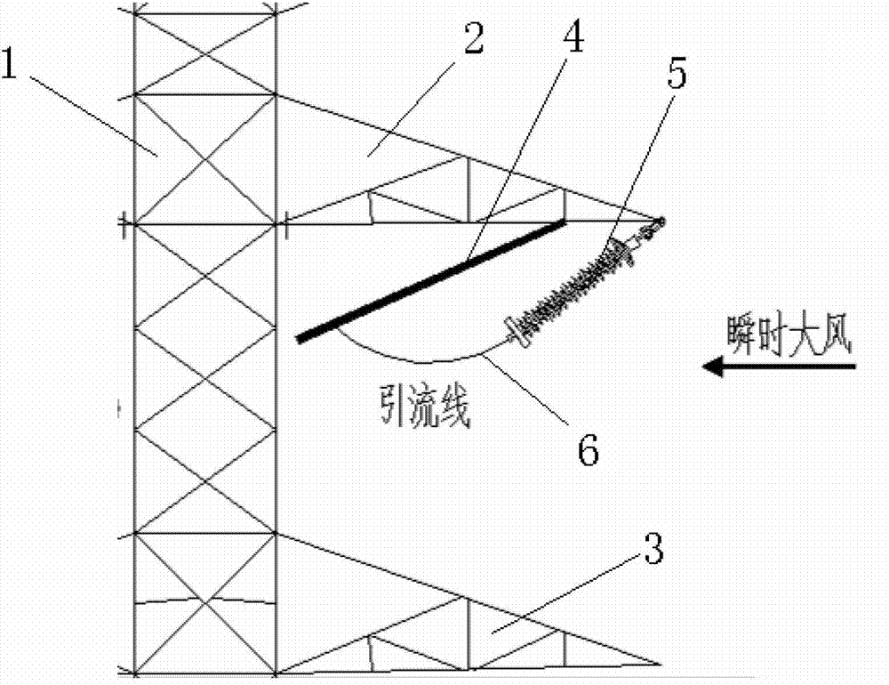
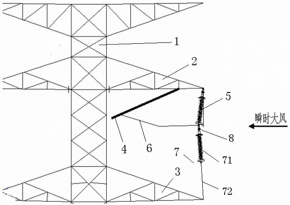
[0038] Such as figure 2 As shown, a high-voltage AC line tension tower drainage fitting provided by the present invention includes a jumper string 5, and the jumper string 5 is arranged between two tension strings 4 connected to the two ends of the drainage line 6, The upper end of the jumper string 5 is hinged with the upper cross arm 2 of the strain tower 1, and its lower end is connected with the drain wire. The lower end of the jumper string is also provided with a limit device for limiting the maximum swing angle of the jumper string. One end is hinged with the lower cross arm of the strain tower, and the other end is hinged with the lower end of the jumper string, and the maximum swing angle of the jumper string is limited to 5°-7°.

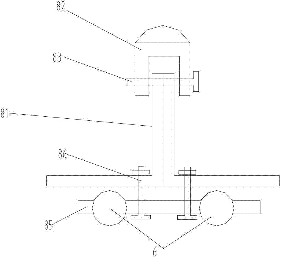
[0039] The limit device includes a limit jumper string and an elastic stay wire. The upper end of the limit jumper string is connected to the lower end of the jumper string through a connecting device, and its lower end is fixedly connecte...


PUM


Abstract

The invention discloses a drainage armour clamp of a high voltage alternative current circuit tension resisting tower. The drainage armour clamp comprises a jumper wire string, wherein the jumper wire string is arranged between two tension resisting strings which are connected with two ends of a drainage wire; the upper end of the jumper wire string is hinged with the upper cross arm of the tension resisting tower; the lower end of the jumper wire string is connected with the drainage wire; a limiting device for limiting the maximum swinging angle of the jumper wire string is further arranged at the lower end of the jumper wire string; one end of the limiting device is hinged with a cross arm below the tension resisting tower; and the other end of the limiting device is hinged with the lower end of the jumper wire string. The drainage armour clamp ensures that the gale flashover is prevented under the condition that instantaneous gale which exceeds the engineering designed air velocity happens partially nearby the drainage wire by additionally arranging the limiting device for limiting the swinging angle of the jumper wire string at the lower end of the jumper wire string; and meanwhile the length of the cross arm is shortened, so that the engineering cost is saved.

Description

technical field [0001] The invention relates to the technical field of high-voltage AC transmission line iron tower drainage, in particular to a high-voltage AC line tension tower drainage fitting. Background technique [0002] Strain tower drainage is a wire connection means to ensure the insulation between the live wire and the iron tower when the transmission line changes direction. [0003] At present, the drainage methods of the tension tower of the transmission line mainly adopt three kinds of drainage technical schemes: direct jumping, adding insulating jumping strings with counterweights and hard jumping wires. [0004] Among them, the direct jump drainage method is to directly connect the wires on both sides of the strain tower through the drainage line; the ordinary tension tower adopts the form of adding jumpers and counterweights on the drainage line to increase the weight of the drainage line and reduce the drainage line The maximum wind deflection; the hard ju...

Claims


Application Information

Patent Timeline
Patent Type & Authority Patents(China)
IPC IPC(8): H02G7/14
Inventor 陈楠康东升宋立军刘晶
Owner STATE NUCLEAR ELECTRIC POWER PLANNING DESIGN & RES INST CO LTD
Why Eureka
Try Eureka