Binding resistor configuration structure for three-phase integrated on-load voltage regulation switch

A technology of voltage regulating switch and configuration structure, which is applied in the direction of electrical component structure association, transformer/inductor components, circuits, etc., can solve the problems of high voltage level of tap changer, difficult to handle insulation problems, and large size of binding resistance. , to achieve the effect of improving electrical performance, saving internal space, and meeting insulation distance requirements

Pending Publication Date: 2018-09-11
BAODING TIANWEI BAOBIAN ELECTRICAL
View PDF0 Cites 1 Cited by
  • Summary
  • Abstract
  • Description
  • Claims
  • Application Information

AI Technical Summary

Problems solved by technology

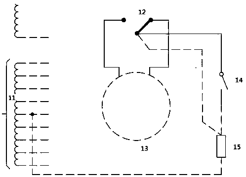
[0010] Although the on-load tap-changer chooses to use three large resistors as tie-in resistors, the size of the tie-in resistors is still large due to the large capacity of the transformer and the limited circulating current between the taps, and the space of the transformer is limited. The grade is high, and the insulation problem near the switch is not easy to deal with

Method used


Image

  • Binding resistor configuration structure for three-phase integrated on-load voltage regulation switch
  • Binding resistor configuration structure for three-phase integrated on-load voltage regulation switch
  • Binding resistor configuration structure for three-phase integrated on-load voltage regulation switch

Examples


Embodiment Construction

[0021] The present invention will be further described through the embodiments below in conjunction with the accompanying drawings.

[0022] A tie resistor configuration structure for a three-phase integrated on-load tap changer, including A phase tie resistor 1, B phase tie resistor 2, C phase tie resistor 3, on-load tap changer 4, iron core lower web 5, and insulating support plate 6 and supporting wire clamp 7, the C-phase tie-up resistor 3 is arranged at the bottom of the on-load tap-changer 4, the A-phase tie-in resistor 1 and the B-phase tie-in resistor 2 are installed at the lower part of the on-load tap-changer 4, and the transformer core clip On the insulating support plate 6 of the component, the lower web plate 5 of the iron core is arranged at the lower end of the insulating support plate 6, and the vertical directions of the A-phase binding resistor 1, the B-phase binding resistor 2, and the C-phase binding resistor 3 are on the same horizontal plane, forming a "pr...


PUM


Abstract

The invention relates to a binding resistor configuration structure for a three-phase integrated on-load voltage regulation switch and belongs to the technical field of transformer equipment. According to the technical scheme, a C-phase binding resistor (3) is arranged at the bottom of an on-load tap switch (4), an A-phase binding resistor (1) and a B-phase binding resistor (2) are arranged at thelower portion of the on-load tap switch (4), on an insulation supporting plate (6) of a transformer core clamp, and a core lower web (5) is arranged at the lower end of the insulation supporting plate (6); the A-phase binding resistor, the B-phase binding resistor and the C-phase binding resistor are located on the same horizontal plane in the vertical direction and arrayed in a triangular shape,form star-shaped connection through a binding resistor connection cable (8), and then are connected to tap positions and neutral points of all phases. According to the binding resistor configurationstructure, on one hand, the insulation distance requirements of each phase binding resistor of the on-load switch are met, and the electrical performance is improved; on the other hand, the internal space of a transformer body is saved, and the manufacturing cost of a transformer is lowered.

Description

technical field [0001] The invention relates to a tie-in resistance arrangement structure of a three-phase integrated on-load tap changer, and belongs to the technical field of transformer equipment. Background technique [0002] The on-load tap changer is used to change the tap of the transformer under the condition of load, so as to achieve the purpose of regulating voltage. There must be an impedance during the changeover to limit the circulating current between taps. Resistive on-load tap-changer is a kind of switch in oil, resistance transition, buried type on-load tap-changer. Resistive on-load tap-changer is an advanced and commonly used switch. [0003] When the change-over selector operates, the tap winding is not connected for a short period of time, and the voltage on the winding is determined by the capacitance and voltage between it and the surrounding winding or the wall of the fuel tank. Certain winding layouts, voltages and capacitive induced voltages gene...

Claims


Application Information

Patent Timeline
Patent Type & Authority Applications(China)
IPC IPC(8): H01F29/02H01F27/40
CPCH01F29/02H01F27/402
Inventor 杨静赵丽杰何磊张伟关雯缤于海飞
Owner BAODING TIANWEI BAOBIAN ELECTRICAL
Why Eureka
Try Eureka