Marine floating oil collecting ship

An oil slick and floating hull technology, applied in special-purpose ships, ships, motor vehicles, etc., can solve the problems of intermittent operation, small collection range, inability to effectively deal with the position change of oil slicks, etc., so as to prolong working time and save internal space. , to avoid the effect of re-diffusion of oil layer

Inactive Publication Date: 2009-12-09
SHANGHAI JIAO TONG UNIV +1
View PDF1 Cites 18 Cited by
  • Summary
  • Abstract
  • Description
  • Claims
  • Application Information

AI Technical Summary

Problems solved by technology

Its shortcomings mainly lie in: it is obviously affected by the waves on the sea surface, and it cannot effectively deal with the change of the position of the oil slick caused by the change of the water level; it is intermittently operated and the efficiency is not high; it can only realize the collection of oil and water, and cannot prevent the spread of the oil slick; The collection area is small, and the treatment area is easily re-covered by other surrounding oil slicks

Method used


Image

  • Marine floating oil collecting ship
  • Marine floating oil collecting ship
  • Marine floating oil collecting ship

Examples


Embodiment Construction

[0025] The embodiments of the present invention are described in detail below in conjunction with the accompanying drawings: this embodiment is implemented on the premise of the technical solution of the present invention, and detailed implementation methods and specific operating procedures are provided, but the protection scope of the present invention is not limited to the following the described embodiment.

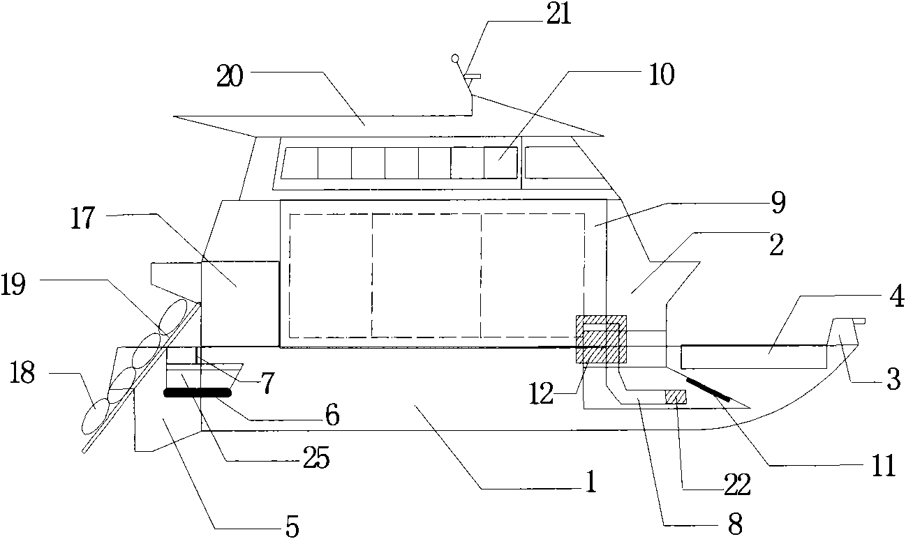
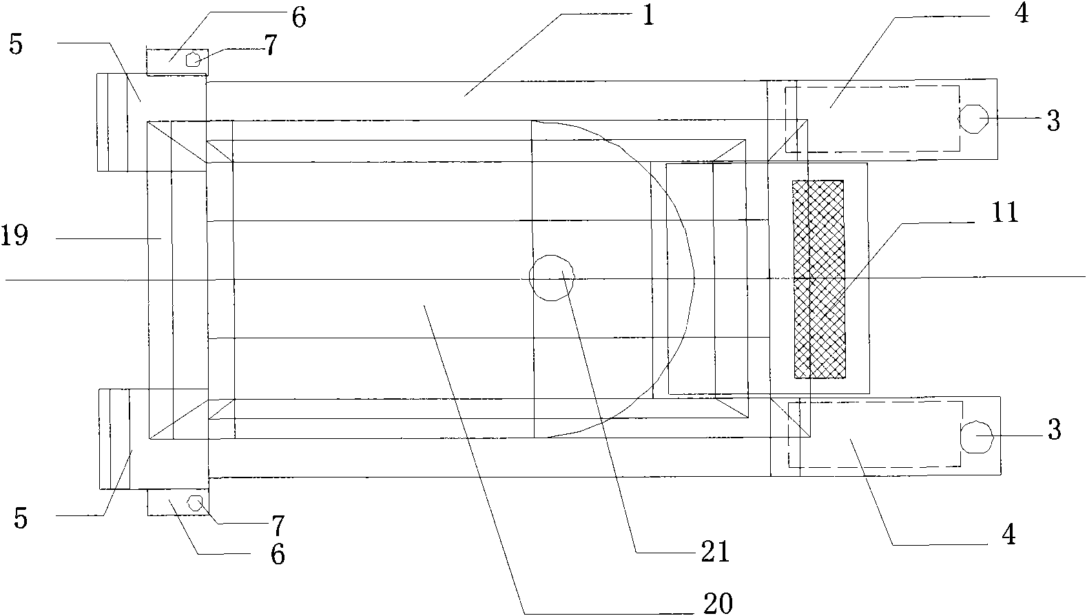
[0026] like figure 1 and 2 As shown, the present embodiment consists of a floating hull 1 and a main hull 2. The floating hull 1 has a certain draft to provide the required buoyancy of the device. The main hull 2 ​​is supported by the floating hull 1 and is located above the water surface.

[0027] There are two pontoon hulls 1, and the equipments thereon are arranged symmetrically about the mid-longitudinal section of the device. The deck at the bow of the floating hull 1 is provided with a reagent spraying device 3, and the deck at the tail is provided with a self...


PUM


Abstract

The invention is a marine floating oil collecting ship in the technical field of ship engineering, comprising floating ship bodies and a main ship body, wherein the main ship body is fixed on two symmetrically placed floating ship bodies; each floating ship body comprises a reagent spraying device, a water spraying propeller, a self-running vehicle platform, a self-running vehicle, an oil containment boom, an oil containment boom bracket and a floating ship body storage chamber; the floating ship body storage chamber is installed in a compartment of the floating body ship; the reagent spraying device is installed on the floating ship body; the water spraying propeller is installed under the tail part of the floating body ship; the self-running vehicle platform is installed on the tail part of the floating ship body; the self-running vehicle is installed on the self-running vehicle platform on which a control signal receiver and a power device are installed; the oil containment boom bracket is fixed on the self-running vehicle platform; one end of the oil containment boom is fixedly connected with the self-running vehicle, and the other end is fixedly connected with the oil containment boom bracket. The invention can high-efficiently and globally handle large area marine oil leakage accident and is combined into the systematic marine floating oil treating technology, thereby realizing the integrated handling of the single device to the marine oil leakage accident.

Description

technical field [0001] The invention relates to an oil slick treatment ship in the technical field of ship engineering, in particular to an offshore oil slick collection ship. Background technique [0002] The world's oil transportation mainly relies on maritime transportation. According to statistics, oil spill accidents caused by oil tankers running aground, colliding, rocking, fire and explosion, and damage to the structure of the hull itself are about 200,000 to 400,000 tons of crude oil every year; As more and more offshore drilling platforms and offshore oil pipelines are built one after another, there are also hidden dangers to the environment or their own structures. Explosions on platforms or leakage of oil pipelines may occur, resulting in crude oil spill accidents. [0003] Crude oil spills at sea not only waste increasingly scarce oil resources, but may also lead to international disputes. What is more serious is that the leaked crude oil floating on the ocean or...

Claims


Application Information

Patent Timeline
Patent Type & Authority Applications(China)
IPC IPC(8): B63B35/32
Inventor 王磊封培元史琪琪万忠邵伟
Owner SHANGHAI JIAO TONG UNIV
Why Eureka
Try Eureka