Transmission system of rotary-type heat exchanger

A technology of transmission system and heat exchanger, applied in the field of transmission system, can solve problems such as inability to repair and replace faulty motors online, and achieve the effect of improving equipment reliability

Active Publication Date: 2014-04-09
SHANGHAI BOILER WORKS
View PDF4 Cites 0 Cited by
  • Summary
  • Abstract
  • Description
  • Claims
  • Application Information

AI Technical Summary

Problems solved by technology

[0017] The purpose of the present invention is to solve the problem that it is impossible to repair and replace the faulty motor on-line, and to change the rotation direction of the heat exchanger rotor, and to provide a transmission system of a rotary heat exchanger with high reliability and simplified operation and maintenance.

Method used


Image

  • Transmission system of rotary-type heat exchanger
  • Transmission system of rotary-type heat exchanger
  • Transmission system of rotary-type heat exchanger

Examples


Embodiment 1

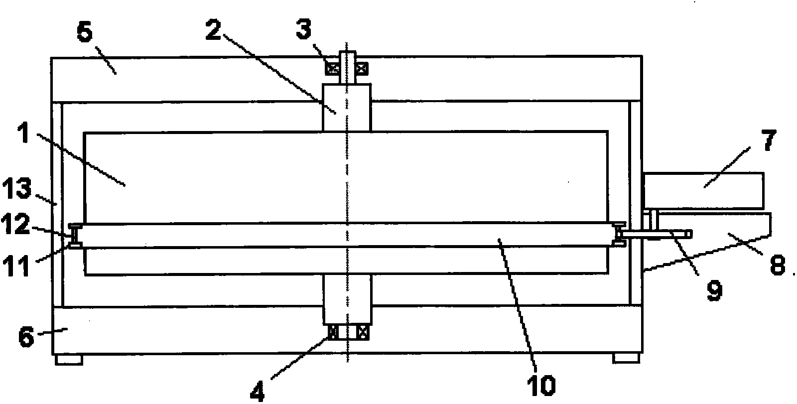
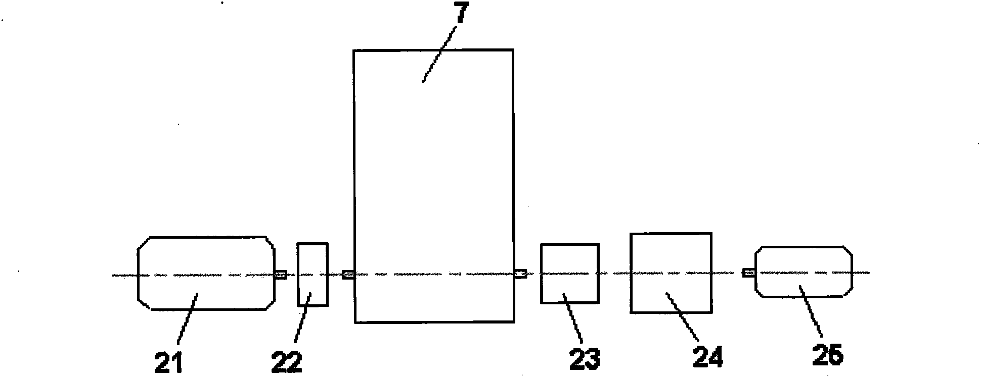
[0042] Such as Figure 5 Shown is the structural schematic diagram of the basic rotary heat exchanger transmission system. The present invention is a transmission system of a rotary heat exchanger. One end of the third reducer 30 is connected to one end of the first magnetic coupling device 32, and the other end of the first magnetic coupling device 32 is connected to the rotating end of the second main motor 31. Connect, the other end of the second main motor 31 is connected with the control box 44, the other end of the third reducer 30 is connected with one end of the second magnetic coupling device 33, the other end of the second magnetic coupling device 33 is connected with the second auxiliary motor 43 The rotating end of the second auxiliary motor 43 is connected with the control box 44, and the control box 44 is connected with the rotor speed measuring system 45 and the power supply 46. Through the control box 44, the steering of the heat exchanger can be changed onlin...

Embodiment 2

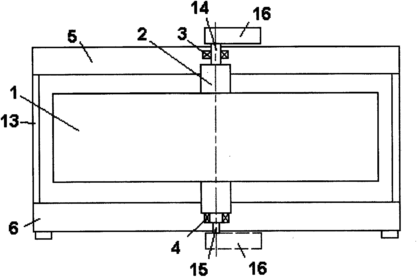
[0051] Such as Figure 6 Shown is a schematic structural diagram of a complete rotary heat exchanger drive system. The present invention is a transmission system of a rotary heat exchanger, and the first magnetic coupling device 32 is the second magnetic coupling device 33 . The difference with the ordinary system (i.e. the basic rotary heat exchanger transmission system in Embodiment 1) is that this system does not distinguish between the main and auxiliary drives, and only lies in changing the magnetic coupling 34 on the main driving side of the basic type into a permanent magnetic regulator. Speed ​​type magnetic coupler 40, and configure corresponding adjustment actuator 38 (including executive motor 37 and manual disk 36), other components are the same as common type system.

[0052] The present invention has been verified in practical engineering, and has been run and tested for enough time, and has good application value and prospect.

[0053] (1) Start-up protection:...


PUM


Abstract

The invention discloses a transmission system of a rotary-type heat exchanger, wherein the transmission system of the rotary-type heat exchanger comprises a third speed reducer. The transmission system of the rotary-type heat exchanger is characterized in that one end of the third speed reducer is connected with one end of a first magnetic force coupling device, and the other end of the first magnetic force coupling device is connected with a rotary end of a second main motor; the other end of the second main motor is connected with a control box; the other end of the third speed reducer is connected with one end of the second magnetic force coupling device; the other end of the second magnetic force coupling device is connected with a rotary end of a second auxiliary motor; the other end of the secondary auxiliary motor is connected with the control box; and the control box is connected with a rotor speed measuring system and a power supply. The transmission system of the rotary-type heat exchanger provided by the invention has the characteristics of high reliability, simplified running and maintaining operation, and the like.

Description

technical field [0001] The invention relates to a transmission system of a rotary heat exchanger, belonging to the technical field of rotary heat exchanger equipment. Background technique [0002] The rotary heat exchanger is the core component of the equipment. Its main function is to absorb the waste heat discharged from the front section of the boiler to heat the boiler combustion and pulverized coal conveying air, or to reheat the flue gas cooled by the desulfurization system. Large rotary heat exchangers include air preheaters and flue gas-flue gas heat exchangers. The weight of the rotor filled with heat exchange surfaces can reach hundreds of tons, and a specially designed transmission system is used to ensure its continuous rotation. Since the rotation of the air preheater is related to the normal operation of the boiler system, the reliability of its work is very important to the boiler unit. [0003] Traditionally designed rotary heat exchangers generally use the...

Claims


Application Information

Patent Timeline
Patent Type & Authority Patents(China)
IPC IPC(8): H02K51/00H02K7/10
Inventor 蔡明坤张建国王勇徐雪元张翔吴乃新
Owner SHANGHAI BOILER WORKS
Why Eureka
Try Eureka