Roller backstop

A backstop and backstop technology, applied in the direction of brake type, automatic brake, mechanical energy control, etc., can solve the problems of fast wear and tear of backstop facilities, complex manufacturing structure, high production cost, and achieve reduced production cost, easy parts processing, The effect of a low number of parts

Active Publication Date: 2013-11-27
GUANGXI ZHENGYUAN ELECTRICAL MACHINE
View PDF8 Cites 4 Cited by
  • Summary
  • Abstract
  • Description
  • Claims
  • Application Information

AI Technical Summary

Problems solved by technology

[0002] In order to ensure the life safety of equipment and people in case of shutdown or sudden power failure, it is more and more common to install backstop devices on operating parts, and there are more and more types. The common ones are belt backstop, roller Type backstops, wedge-type backstop bearings, ratchet pawl backstop devices with tension and compression springs, etc., have indeed played their due role in production for a long period of time. The disadvantage is that these backstops The facilities have different degrees of fast wear, complex manufacturing structure, high production cost, bulky appearance, and require the backstop to be lubricated and sealed.

Method used


Image

  • Roller backstop
  • Roller backstop
  • Roller backstop

Examples


Embodiment 1

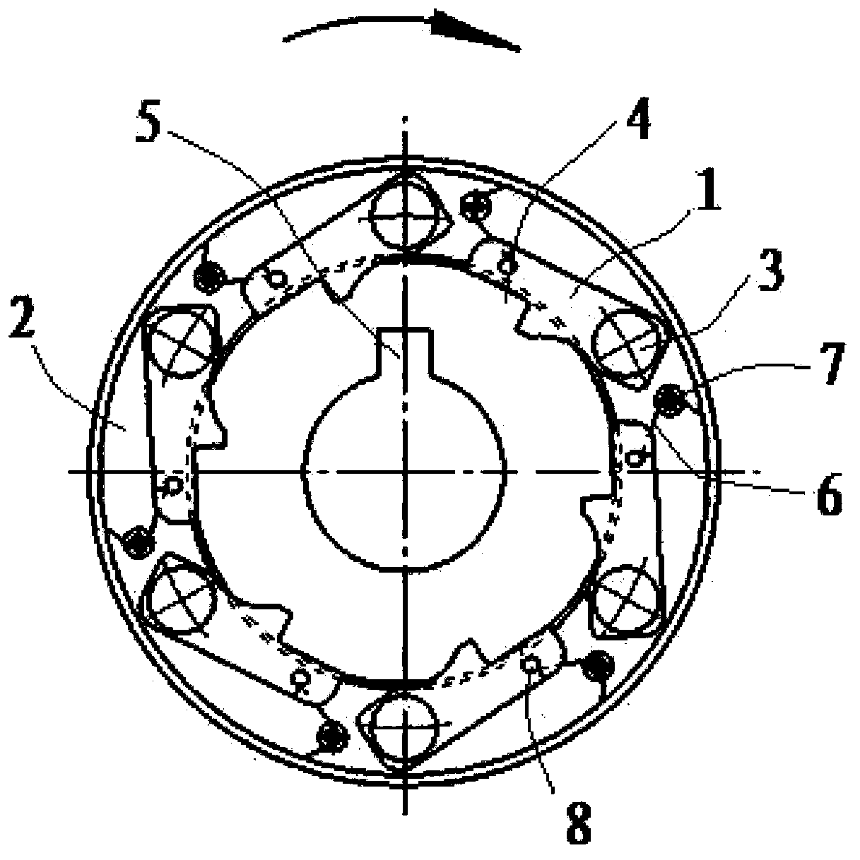
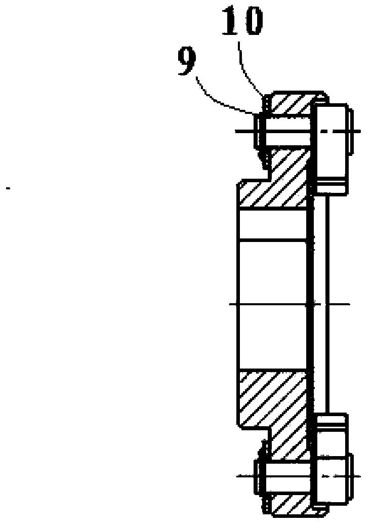
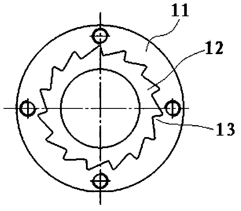
[0021] Such as Figure 1-Figure 4 , a drum backstop, comprising: a pawl plate and a ratchet plate, the pawl plate includes: a flange plate 2, a pawl 1, an elastic steel wire 6; the ratchet plate includes: a backstop wheel 12 and a backstop wheel fixed plate 11 , wherein: the middle hole of the flange 2 has a keyway 5, the pawl 1 surrounds the flange 2 and one end is connected to the front of the flange 2 near the edge of the circumference, and the other end of the pawl 1 has a 90° There is a small hole on one side of tooth mouth 4, 90° tooth mouth 4, and elastic steel wire 6 is installed on the front of flange 2 between ratchet 1 near the peripheral edge, and one end of elastic steel wire 6 is connected with the small hole at the tooth mouth end of ratchet 1 , the other end is fixed on the edge of the flange 2; the edge of the backstop wheel 12 has a 90° backstop opening 13, and the backstop wheel 12 and the backstop wheel fixed plate 11 are fixed by face-to-face center symmet...

Embodiment 2

[0028] Take the assembly on the motor as an example, as attached Figure 4 , the ratchet disc 16 is installed on the inner wall of the end cover of the motor 17, the ratchet disc 16 is fixed, and the ratchet disc 15 is fixed on the motor shaft 18 through the flat key 14. Swing it to the peripheral edge of the flange and disengage from the backstop wheel 12 of the ratchet disc 16. When the motor 17 needs to be backstopped due to various factors, the 90° tooth mouth 4 of the ratchet 1 is due to the elastic steel wire 6. function, quickly return to the working position, and can quickly mesh with the 90° backstop 13 of the backstop wheel 12, and the 90° tooth opening 4 of the ratchet 1 is pressed against the 90° backstop 13 of the backstop wheel 12 , because the ratchet disc 16 is fixed on the motor 17, it can quickly stop reversing and realize the backstop effect.

[0029] The drum backstop provided by the present invention has a simple and lightweight structure, and does not ne...


PUM


Abstract

The invention relates to a roller backstop. The roller backstop comprises a pawl disc and a ratchet disc. The pawl disc comprises a flange, pawls and elastic steel wires. The ratchet disc comprises a backstopping wheel and a backstopping wheel fixing disc. The roller backstop is characterized in that a key groove is opened at a central hole of the flange; the pawls surround the flange circumferentially, one end of each pawl is connected to a position of the front of the flange, which is close to the circumferential edge, a 90-degree tooth opening is formed in the other end of each pawl, and a small hole is formed in one side of each 90-degree tooth opening; the elastic steel wires are arranged at the positions in the front of the flange between the pawls, which are close to the circumferential edge, one end of each elastic steel wire is connected with each small hole in each pawl tooth opening end, and the other end is fixed at the edge of the flange; 90-degree backstopping openings are formed in the edge of the backstopping wheel, and the backstopping wheel and the backstopping wheel fixing disc are welded and fixed in a face-to-face center symmetrical mode. The roller backstop is simple and light in structure and in no need of lubrication or sealing.

Description

technical field [0001] The invention relates to a drum backstop. technical background [0002] In order to ensure the life safety of equipment and people in case of shutdown or sudden power failure, it is more and more common to install backstop devices on operating parts, and there are more and more types. The common ones are belt backstop, roller Type backstops, wedge-type backstop bearings, ratchet pawl backstop devices with tension and compression springs, etc., have indeed played their due role in production for a long period of time. The disadvantage is that these backstops The facilities have the disadvantages of fast wear, complex manufacturing structure, high production cost, bulky appearance, and require the backstop to be lubricated and sealed to varying degrees. [0003] Therefore, invent a kind of simple in structure, light and handy, needn't backstop lubricated, sealing backstop seems to be increasingly needed. Contents of the invention [0004] The purpose...

Claims


Application Information

Patent Timeline
Patent Type & Authority Applications(China)
IPC IPC(8): F16D59/00H02K7/10
Inventor 刘满庆刘海东杜飚梁家强邓奇亨方能福
Owner GUANGXI ZHENGYUAN ELECTRICAL MACHINE
Why Eureka
Try Eureka