
Light-emitting diode (LED) driving power supply and LED lighting lamp

A LED driving and LED lighting technology, which is applied in the direction of electric light source, lighting device, lamp circuit layout, etc., can solve the problems of large size, large power loss of power switching tube secondary rectification circuit devices, and many electronic components, etc., to achieve Solve the effects of inconsistency, increased service life, and fewer electronic components

Inactive Publication Date: 2012-10-24
中山天外天防爆照明有限公司 +1
View PDF9 Cites 17 Cited by
  • Summary
  • Abstract
  • Description
  • Claims
  • Application Information

AI Technical Summary

Problems solved by technology

[0007] The number of stages of this switching power supply: there are single-stage (Single-stage, also known as single-stage), two-stage (also known as two-stage), three-stage (also known as three-stage), circuit structure is very complicated, The material cost and production cost are very high; the power switch tube, high-frequency transformer, and secondary rectifier circuit components have large electrical losses, severe self-heating, and low power supply efficiency; the high self-heating of the driving power supply is not conducive to the structural design of LED lamps. High heat generation will also affect the service life of the LED chip and increase the light decay of the LED; this switching power supply circuit uses many electronic components and large size, which reduces the reliability of the power supply and is not conducive to the installation and fixation of the built-in power supply

Method used


Image

  • Light-emitting diode (LED) driving power supply and LED lighting lamp
  • Light-emitting diode (LED) driving power supply and LED lighting lamp
  • Light-emitting diode (LED) driving power supply and LED lighting lamp

Examples


Embodiment Construction

[0044] In order to describe the technical content, structural features, achieved goals and effects of the present invention in detail, the following will be described in detail in conjunction with the embodiments and accompanying drawings.

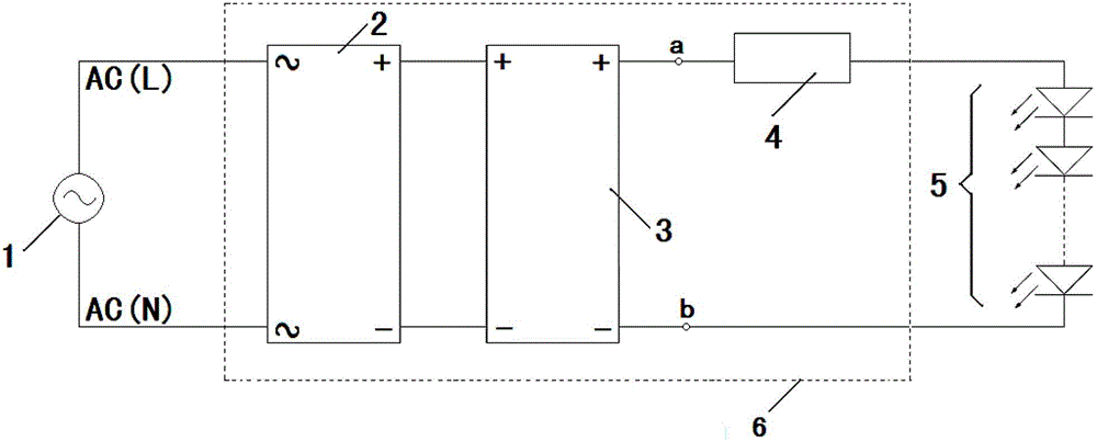
[0045] see figure 1 , in this embodiment, the LED lighting fixture includes an LED light source chip 5, an LED light source chip substrate (not shown), an LED driving power supply 6, and a lamp housing (not shown); the LED light source chip 5 is mounted on the LED light source chip substrate to form The LED lamp board is fixedly installed in the housing of the lamp.

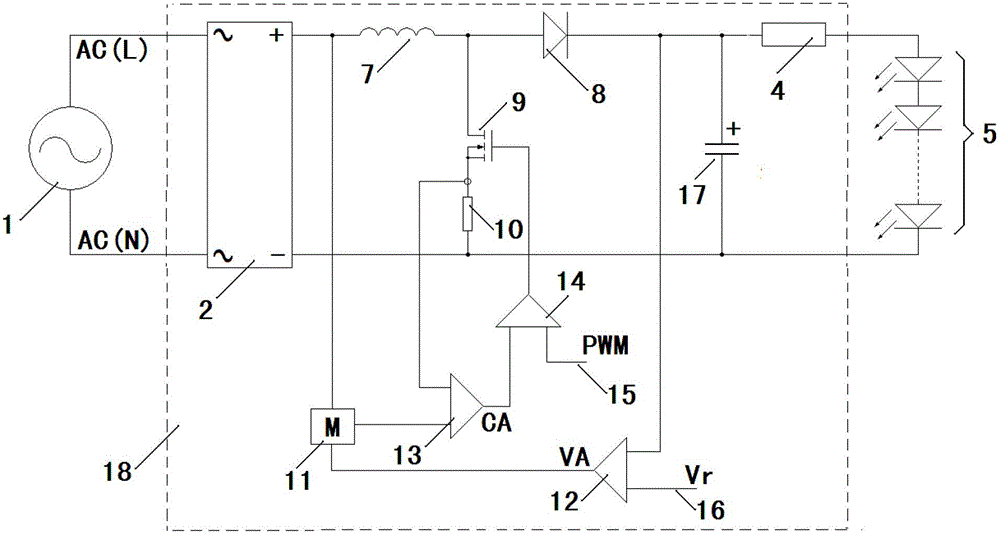
[0046] The LED driving power supply 6 of the LED lighting fixture includes a bridge rectifier circuit 2, a power factor corrector circuit 3 (referred to as a PFC circuit, and the English full name is "Power Factor Correction"), a constant current circuit 4, and an output terminal of the bridge rectifier circuit 2 Connect the input terminal of the power factor corrector circu...


PUM


Abstract

The invention discloses a light-emitting diode (LED) driving power supply and an LED lighting lamp. The LED lighting lamp comprises an LED light source chip, a substrate, the LED driving power supply and a lamp casing. The LED light source chip is arranged on the substrate to form an LED lamp panel fixedly arranged in the lamp casing. The LED driving power supply comprises a bridge rectifier circuit, a power factor corrector circuit and a galvanostat circuit which are sequentially electrically connected. The input end of the bridge rectifier circuit is used for being connected with an external power supply, and the output end of the galvanostat circuit is connected with the LED light source chip. The rated forward voltage of the LED light source chip is no higher than the direct-current voltage output by the power factor corrector circuit. In the LED lighting lamp, high-voltage direct-current voltage is subjected to constant current and then directly drives the LED light source chip. The LED driving power supply is simple in structure, small in loss, high in efficiency and strong in generality, and therefore general utilization of the LED lighting lamp can be achieved.

Description

technical field [0001] The invention relates to the field of LED lighting, in particular to an LED driving power supply and an LED lighting lamp. Background technique [0002] The development speed of LED lighting technology is really unexpected. The application field of LED is expanding rapidly. LED enterprises are springing up like mushrooms. Some world-renowned lighting leading enterprises have made a strong attack to seize the Chinese LED lighting market. The field of lighting application products is showing its strength; although the application market of LED lighting technology is very large and the application field is very wide, but now the standards of LED lighting products in various countries and manufacturers are not uniform, the specifications are inconsistent, basically they cannot be used universally, and there is no interaction. interchangeable, not standardized. [0003] LED lighting products are basically not universal, and there is no unified and standard...

Claims


Application Information

Patent Timeline
IPC IPC(8): H05B37/02
Inventor 王中美
Owner 中山天外天防爆照明有限公司
Learn More