Infusion apparatus

A technology for infusion sets and infusion tubes, which is applied in the direction of subcutaneous injection devices and devices introduced into the body, etc., which can solve the problems of high production cost, insufficient operation, and air intake in the lower infusion tube, and achieve reduced production costs, simple operation, and economical material effect

Inactive Publication Date: 2012-10-31
戎静华
View PDF0 Cites 4 Cited by
  • Summary
  • Abstract
  • Description
  • Claims
  • Application Information

AI Technical Summary

Problems solved by technology

1. The operation is not simple enough
Every time the dropping funnel needs to open and close the sealing plug before and after exhausting, otherwise, if the dropping funnel shakes or tilts after the exhausting, it is easy to make the gas outlet above the liquid level, so that the dripping funnel continues to exhaust, causing the dripping funnel The dropping funnel loses the function of observing the dripping speed due to excessive exhaust gas
2. High production cost
Because the material cost of high-hardness plastics and soft sealing rubber for infusion sets that meet the Pharmacopoeia standards is several times higher than that of soft plastics, the cost of making such dripping funnels and stoppers is relatively high.
3. It is easy to cause air intake in the lower infusion tube
Because the dripping speed is too fast during the infusion, air bubbles will be generated in the infusion solution in the drip funnel, thus the phenomenon of air intake in the lower infusion tube will occur. Appearance of phenomenon

Method used


Image

  • Infusion apparatus
  • Infusion apparatus
  • Infusion apparatus

Examples


Embodiment 1

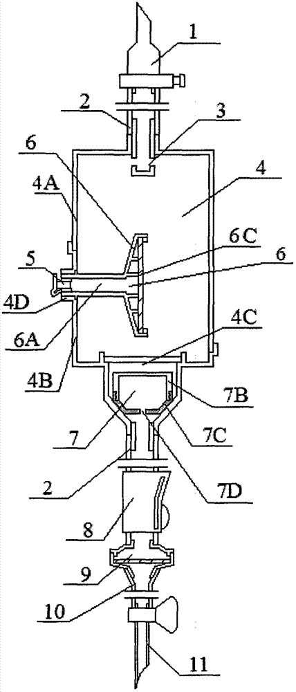
[0018] Such as figure 1 What is shown is a kind of infusion device, the bottle stopper piercer 1 is connected with the infusion tube 2, the infusion tube 2 is connected with the dripping funnel 4, and an infusion dripping tube whose lower part extends into the dripping funnel cavity is installed on the neck of the upper end of the dripping funnel 4 3. In the part of the infusion dripping pipe 3 extending into the cavity of the dripping funnel, one or more spouts are only provided at the position towards the side wall of the dripping funnel 4. The shape of the dripping funnel 4 under the neck of the upper end is arranged in order from top to bottom: first, there are two circular cylinders with a large diameter and a small diameter on the same axis, and then a rounded table on the same axis as them The ring body is the lower end neck of the dropping funnel 4 at last. A circular grid partition plate 4C is also provided between the large-diameter circular cylinder and the small-d...

Embodiment 2

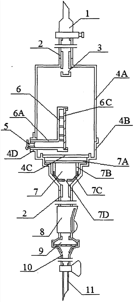
[0027] Such as figure 2 What is shown is a kind of infusion device, the bottle stopper piercer 1 is connected with the infusion tube 2, the infusion tube 2 is connected with the dripping funnel 4, and an infusion dripping tube whose lower part extends into the dripping funnel cavity is installed on the neck of the upper end of the dripping funnel 4 3. In the part of the infusion dripping pipe 3 extending into the cavity of the dripping funnel, one or more spouts are only provided at the position towards the side wall of the dripping funnel 4. The dripping funnel 4 under the neck of the upper end is arranged in order from top to bottom: first, three coaxial circular cylinders with gradually smaller diameters arranged in sequence from top to bottom, and then a coaxial circular cylinder with them. The rounded platform ring body is the lower end neck of the dropping funnel 4 at last. A circular grid partition plate 4C is also provided between the circular cylinder with the large...

Embodiment 3

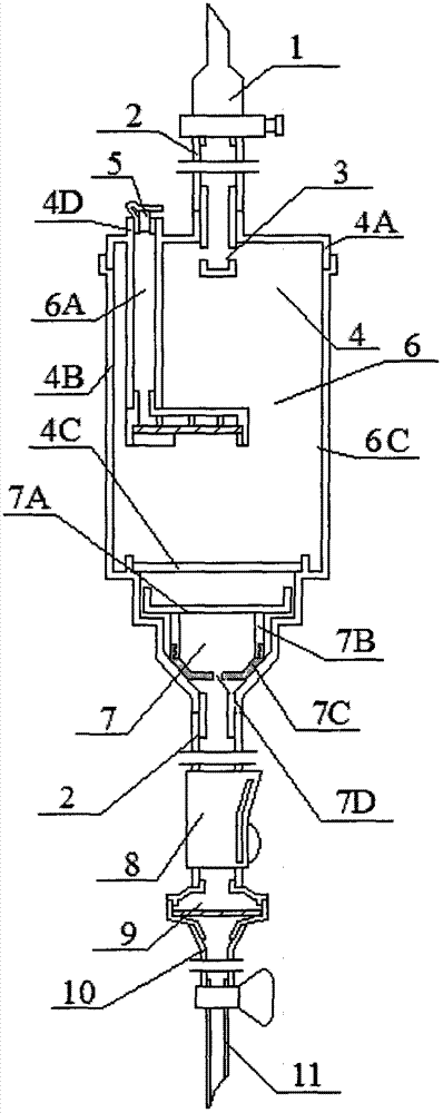
[0032] Such as image 3 What is shown is a kind of infusion device, the bottle stopper piercer 1 is connected with the infusion tube 2, the infusion tube 2 is connected with the dripping funnel 4, and an infusion dripping tube whose lower part extends into the dripping funnel cavity is installed on the neck of the upper end of the dripping funnel 4 3. In the part of the infusion dripping pipe 3 extending into the cavity of the dripping funnel, one or more spouts are only provided at the position towards the side wall of the dripping funnel 4. The dripping funnel 4 located under the neck of the upper end is arranged in order from top to bottom: first, there are three circular cylinders with the same central axis with gradually smaller diameters arranged in sequence from top to bottom, and then a circular cylinder with the same central axis as them. Axle rounded platform ring body, is the lower end neck of dropping funnel 4 at last. A circular grid partition plate 4C is also pr...


PUM


Abstract

The invention discloses an infusion apparatus which comprises a bottle stopper puncture outfit, an infusion tube, an infusion dripping tube, a dripping bucket, a lower infusion tube, an infusion stopping bucket, a flow regulator, an outer cone joint, a fine infusion tube and an intravenous injection needle and is characterized in that an infusion stopping floating plug is contained at the lower end of the dripping bucket, wherein the lower part of the infusion stopping floating plug is an inverted circular platform or an inverted circular platform ring body, the upper part of the infusion stopping floating plug is formed by adding an upper top cover on a cylinder or a circular ring cylinder, the shape and the size of the lower end of the dripping bucket are matched with those of the infusion stopping floating plug; a waterproof air filter which is connected with a dripping bucket wall through an exhaust tube is installed in the dripping bucket, and a sealing plug is also arranged at one end of the exhaust tube, which is located on the dripping bucket wall. With the adoption of the infusion apparatus, the automatic exhaust of the dripping bucket and influsion stopping after an infusion is wholly dripped can be realized, so that air can be prevented from entering into the infusion tube.

Description

【Technical field】 [0001] The patent of the present invention relates to a disposable medical infusion set, especially suitable for an automatic exhaust and anti-blood infusion set. 【technical background】 [0002] The current automatic exhaust solution for anti-blood infusion sets is limited to installing the liquid stopper in the drip funnel, and opening a hole in the middle of the side wall of the drip funnel / or opening a hole in the drip funnel cover to install in the drip funnel An opening of a pipe extending to the middle of the dropping funnel, on which an air filter is fitted with a watertight air filter membrane and a sealing plug. Although such a design can not only make the dripping funnel exhaust automatically and very quickly, but also make the dripping funnel be automatically sealed after the infusion is drained, preventing the occurrence of blood back. But it also has the following defects. 1. The operation is not simple enough. Every time the dropping funnel...

Claims


Application Information

Patent Timeline
IPC IPC(8): A61M5/40A61M5/38A61M5/14
Inventor 戎静华
Owner 戎静华
Why Eureka
Try Eureka