C-ring mechanical expanding shaft

A mechanical, expanding and shrinking shaft technology, applied in the direction of winding strip, thin material processing, transportation and packaging, etc., can solve the problems of affecting the bending strength of the expanding shaft, high processing cost, reducing shaft strength, etc. The effect of taking accuracy and reliability, reducing processing cost, and improving coiling accuracy

Inactive Publication Date: 2012-10-31
柳燕明
View PDF8 Cites 5 Cited by
  • Summary
  • Abstract
  • Description
  • Claims
  • Application Information

AI Technical Summary

Problems solved by technology

This kind of solid shaft improves the coiling accuracy by narrowing the gap with the core tube, so the processing cost of the core tube is high, and the reduction of the gap is contradictory to the lightness of the shaft. It is often used in thin core tubes, wide In the coiling work of heavy coils, the disadvantages are the poor coiling accuracy and the key on the end of the core tube, which is inconvenient for the adjustment and operation of the core tube.
[0005] The other one is the airbag expansion shaft with expansion and contraction function in traditional applications. Its advantage is that the core tube is easy to adjust and center. The disadvantage is that due to the compressibility of the gas, the coiled material during coiling will run out radially. , thus affecting the improvement of accuracy
There are 5 to 12 deep grooves on the circumference of the commonly used spindle tube to install the air bag, which reduces the strength of the shaft without coagulation, and increases its own weight. Suspension and pumping the shaft will cause the shaft to bend and deform, and there is also a shaft expansion force. Small, easy to slip, airbag leakage, expansion strip deformation and no retraction, etc.
[0006] In order to solve the shortcomings of the above two structures of the expansion shaft, a mechanical expansion and contraction shaft without a winding core end key has appeared in the background technology, for example: the patent number is: 200620030689.3 utility model "high-precision winding expansion shaft", which The typical structure of slope to slope is used. The expansion force of the shaft of this type of structure depends on the size of the large end of each group of slope blocks and the consistency of the axial size of each set of matching long holes to be installed, so as to ensure that each slope block can be used. Participate in external expansion, which makes the processing cost high. In addition, the bevel block itself has no retraction function. Since there is a matching gap between the expansion core and the long spindle, the radial runout of the expansion shaft affects the improvement of the shaft accuracy.
Due to the large radial size of the inclined-plane expansion block, the design space of the central shaft diameter is compressed, which affects the improvement of the bending strength of the expansion shaft of this type of structure.

Method used


Image

  • C-ring mechanical expanding shaft
  • C-ring mechanical expanding shaft
  • C-ring mechanical expanding shaft

Examples


Embodiment Construction

[0040] The present invention will be further described below in conjunction with accompanying drawing:

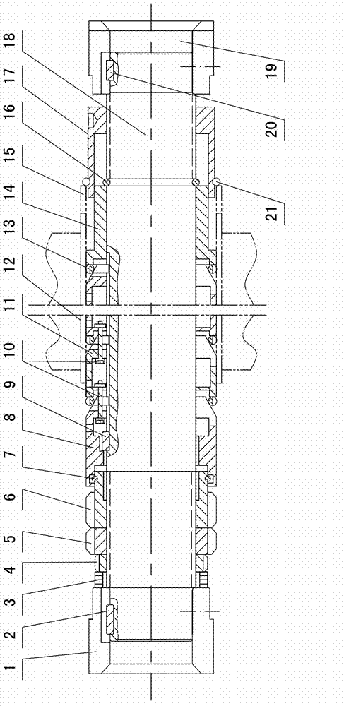
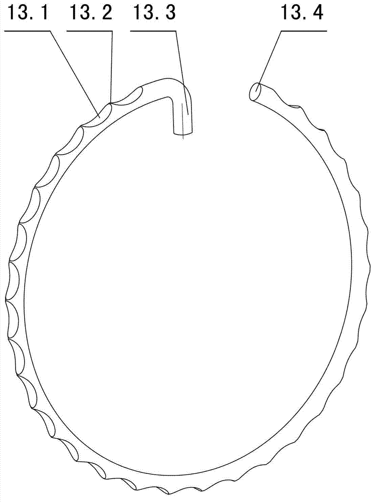
[0041] Such as figure 1 , figure 2 As shown, the C-shaped ring mechanical expansion and contraction shaft includes a cylindrical shaft 18, on which a pushing mechanism, a tapered wedge tube group and a positioning mechanism are sequentially installed from left to right, and the tapered wedge tube group consists of a plurality of side-by-side Composed of cone wedge tubes 11, C-shaped rings 13 are installed between the cone wedge tubes 11 and the pushing mechanism, between two adjacent cone wedge tubes 11, and between the cone wedge tubes 11 and the positioning mechanism. There is a circle head key 13.3 extending along the center of the circle at one end, and the distance between the circle head key 13.3 and the circle tail 13.4 at the other end is 10-50mm. Among them, an anti-skid piece is provided on the outer diameter surface of the C-shaped circle 13, and the anti-skid ...


PUM


Abstract

The invention discloses a C-ring mechanical expanding shaft suitable for processing metal and nonmetal foil / film coils and aluminum belts and foils. An inclined surface-to-circle novel structure which has self-retraction capability, and has a thin blade which is capable of marking deeply is provided, aiming to solve the problems of no foundation and no self-locking in friction caused by the execution expansion strip and the inclined surface expansion block of the existing air bag type or inclined surface-to-inclined surface type mechanical expanding shaft, and the problems of skidding, and low accuracy and low structural strength of the shaft caused thereby. The C-ring mechanical expanding shaft takes the place of the typical structure of inclined surface to inclined surface, and comprises a cylindrical shaft and a plurality of tapered wedge tubes sleeved to the cylindrical shaft. A push-pull nut is turned so that the C-ring having a plurality of blades sleeved to the conical surface are expanded outwards so as to clamp a coiled core tube. Such an inclined surface-to-circle structure is small in radial dimension, so that the strength of the expansion shaft is improved; and due to vanishing of the gap between the circle and the shaft in clamping, the radial jumping error of the shaft is reduced. Besides, the C-ring mechanical expanding shaft is suitable for coiling processing of thin tube core, large breadth and no air pressure source.

Description

technical field [0001] The invention relates to a C-shaped ring mechanical expansion-shrinkage shaft, which belongs to the technical field of metal and non-metal foil and film-like coil material coiling processing shafts. Background technique [0002] In the processing of metal and non-metal foil, film-like coils, aluminum strips, and aluminum foils, the procedure for dividing large-width coils into finished coils of different widths is: first put the core tube on the take-up shaft, Then, the expansion shafts with different expansion methods and different shaft head structures are clamped between the rotating clamping shafts of the decoiler to complete uncoiling and coiling. [0003] At present, there are three types of winding shafts, one is that the core tube is worn on the solid shaft without expansion and contraction function, or there is a key on the end face of the core tube, and it is clamped with a nut. This kind of solid shaft improves the coiling accuracy by narro...

Claims


Application Information

Patent Timeline
Patent Type & Authority Applications(China)
IPC IPC(8): B65H18/04B65H16/02
Inventor 柳燕明
Owner 柳燕明
Why Eureka
Try Eureka