Emergency braking and rheostatic braking combined control device for locomotive brake

A technology of resistance braking and emergency braking, which is applied in electric braking systems, railway braking systems, electric vehicles, etc., can solve the problems of unequipped trains, locomotive wheels locked, non-recoverable, etc., to improve safety and reliability , the effect of avoiding potential safety hazards

Active Publication Date: 2012-11-07
CRRC DALIAN CO LTD
View PDF5 Cites 7 Cited by
  • Summary
  • Abstract
  • Description
  • Claims
  • Application Information

AI Technical Summary

Problems solved by technology

[0006] (1) The function of automatically cutting off resistance braking after emergency braking is realized by the stop signal controlled by the train operation monitoring device, but a large number of locomotives equipped with JZ-7 brakes, especially off-road locomotives, are not equipped with train operation monitoring devices of
[0007] ⑵After emergency braking, the locomotive resistance braking is automatically cut off, and it cannot be restored during emergency braking
[0011] ⑴When the locomotive is in the resistance braking condition, if the resistance braking force is large, once the emergency braking is implemented, the superimposed effect of the two braking forces may cause the wheels of the locomotive to lock
At present, the locomotives that realize this function mainly rely on the joint control of electronically controlled brakes with high cost and on-board microcomputers, but these methods have been modified on some locomotives that have been used in large quantities, such as locomotives equipped with JZ-7 brakes Due to the limitation of vehicle structure, on the one hand, it is very difficult technically, and on the other hand, the economic benefits are not high. Therefore, it is very urgent to carry out limited transformation on the basis of the existing structure to meet the safety requirements of the locomotive under emergency conditions. Require

Method used


Image

  • Emergency braking and rheostatic braking combined control device for locomotive brake
  • Emergency braking and rheostatic braking combined control device for locomotive brake

Examples


Embodiment Construction

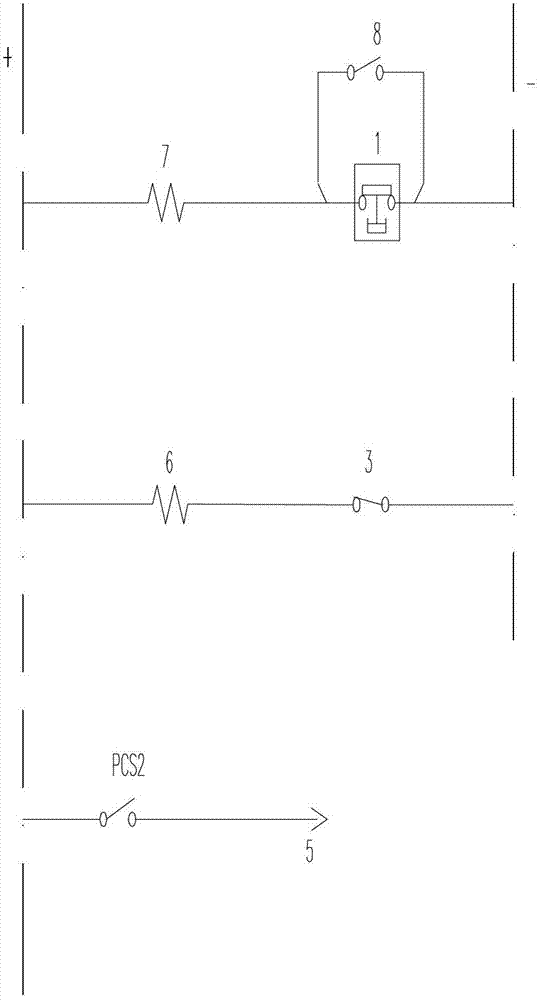
[0032] The invention discloses a joint control device for emergency braking and resistance braking of a locomotive braking machine. After braking, add a logic circuit for resistance braking, and a logic circuit for automatically judging whether to remove the air brake of the locomotive itself according to the magnitude of the resistance braking force.

[0033] like figure 1 As shown, the logic circuit for automatically cutting off locomotive traction and resistance braking after emergency braking is composed of emergency braking pressure switch 1, wiring switch 8 for outputting the stop signal TJ of the train operation monitoring device, intermediate relay and power cutting Composed of relay PCS; the emergency braking pressure switch 1 is used to judge whether the locomotive has implemented emergency braking. When the locomotive is running normally, the pressure switch 1 is in the disconnected state; 1 is closed; after the emergency brake pressure switch 1 is connected in par...


PUM


Abstract

The invention discloses an emergency braking and rheostatic braking combined control device for a locomotive brake. The device comprises a logic circuit used for automatically cutting off locomotive traction and rheostatic braking after emergency braking, a logic circuit used for re-performing rheostatic braking after emergency braking and automatic cutoff of rheostatic braking and a logic circuit used for automatically judging whether to cut off intrinsic air braking of the locomotive or not according to rheostatic braking force. Safety reliability of the locomotive in emergency can be improved by the emergency braking and rheostatic braking combined control device. A function of automatic cutoff of locomotive traction and rheostatic braking after emergency braking of the locomotive is realized; a function of reapplying rheostatic braking force according to needs after emergency braking and automatic cutoff of rheostatic braking; wheel locking of the locomotive caused by superposition of rheostatic braking during re-performing of rheostatic braking after emergency braking is prevented; and automatic recovery of intrinsic air braking force of the locomotive can be guaranteed once rheostatic braking fails.

Description

technical field [0001] The invention relates to the field of locomotive manufacturing, in particular to a combined control device for emergency braking and resistance braking of a locomotive brake. Background technique [0002] Existing non-electronically controlled locomotive brakes, such as JZ-7 locomotive brakes still have a large number of locomotives and market demand. This type of locomotive mainly adopts the following two technologies during emergency braking Program: [0003] The first solution of the prior art is to use the resistance braking interlock valve in the JZ-7 brake machine to connect with the control signal of the locomotive resistance braking. When the locomotive implements resistance braking, the resistance braking interlock valve is energized. The JZ-7 brake will cut off the air braking force of the locomotive itself. [0004] The shutdown signal of the train operation monitoring method is connected with the locomotive loading signal, and when the t...

Claims


Application Information

Patent Timeline
Patent Type & Authority Applications(China)
IPC IPC(8): B61H11/14B60L7/08
Inventor 魏宏范家科周静洁刘强赵全福张瑞珍
Owner CRRC DALIAN CO LTD
Why Eureka
Try Eureka