Reverse pedaling brake mechanism for electric bicycle

A braking mechanism and a technology for electric-assisted bicycles, which are applied in bicycle accessories, bicycle brakes, etc., can solve problems such as increased danger and unrealized application.

Inactive Publication Date: 2012-11-07
DONGGUAN HONG LIN IND CO LTD
View PDF7 Cites 8 Cited by
  • Summary
  • Abstract
  • Description
  • Claims
  • Application Information

AI Technical Summary

Problems solved by technology

[0003] When the rider wants to brake, he usually holds the brake lever firmly to drive the brake calipers to brake the rear wheel. However, for some riders with insufficient grip, such as children or the elderly, the old brake The design may not be able to achieve the desired effect, which virtually increases the risk of riding, so the industry has developed a structure that uses the reverse pedal to produce a braking effect, such as US4,261,449 and US5,810,139 The previous patents provide that when the chain is reversed by the crank, the brake mechanism located in the hub shaft is linked to brake the rear wheel; It is indeed applied to electric assist bicycles

Method used


Image

  • Reverse pedaling brake mechanism for electric bicycle
  • Reverse pedaling brake mechanism for electric bicycle
  • Reverse pedaling brake mechanism for electric bicycle

Examples


Embodiment Construction

[0026] In order to describe the structure, features and functions of the present invention in detail, a preferred embodiment is listed and described below with the following drawings.

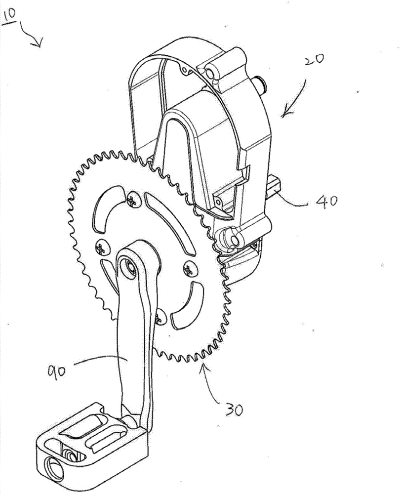
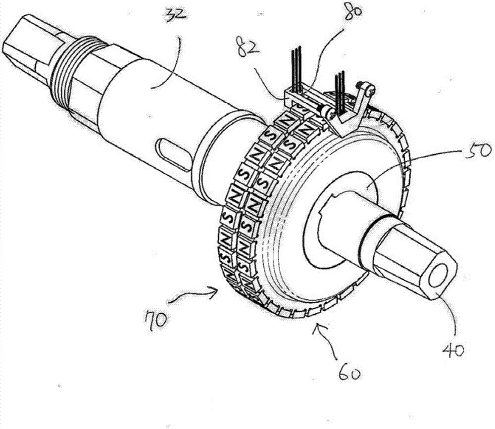
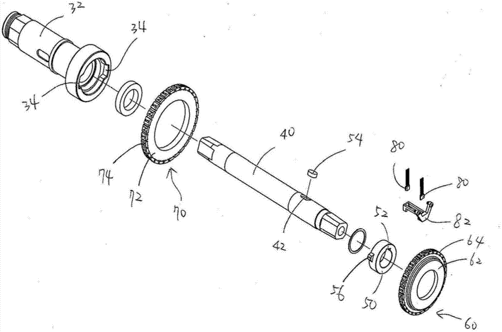
[0027] see Figure 1 to Figure 3 , the reverse braking mechanism 10 provided by a preferred embodiment of the present invention is mainly used in electric power-assisted bicycles, and includes a motor 20, a large chainring 30, a crankshaft 40, a drive ring 50, and two magnetic units 60 , 70, and two magnetic sensors 80.

[0028] The motor 20 is installed on the frame of the electric assist bicycle to provide power assistance. Since the motor 20 is a known technology and is not the focus of the present invention, its detailed structure will not be described here.

[0029] The large toothed plate 30 has a sleeve 32, and the sleeve 32 is connected to the motor 20 through a one-way device (not shown in the figure), so that the large toothed plate 30 can be driven by the motor 20 to rotate in one d...


PUM


Abstract

The invention relates to a reverse pedaling brake mechanism for an electric bicycle. A crank shaft in positive rotation can drive a crankset to rotate positively through a driving ring, then each of the crankset and the driving ring drives a magnet fixing seat to rotate synchronously while dislocation of two magnets fixed onto the two magnet fixing seats is avoided to enable a motor to provide assistance. The crank shaft in reverse rotation can drive the driving ring to rotate relative to the crankset and generates a delay time to enable one of the magnet fixing seat driven by the driving ring to rotate relative to the other magnet fixing seat within the delay time, the two magnets are forcedly dislocated, the assistance provided by the motor is cut off when dislocation between the two magnets is sensed by two magnetic sensors, and finally the driving ring continues to drive the crankset to rotate reversely to brake.

Description

technical field [0001] The invention relates to an electric bicycle, in particular to a reverse brake mechanism of the electric bicycle. Background technique [0002] Generally, when riding a bicycle, the rider presses the pedals with both feet and drives the crankshaft to rotate in a positive way. The chain is used to drive the rear wheel to rotate to achieve the purpose of driving the bicycle forward. [0003] When the rider wants to brake, he usually holds the brake lever tightly to drive the brake calipers to brake the rear wheel. However, for some riders with insufficient grip, such as children or the elderly, the old brake The design may not be able to achieve the desired effect, which virtually increases the risk of riding, so the industry has developed a structure that uses the reverse pedal to produce a braking effect, such as US4,261,449 and US5,810,139 The previous patents provide that when the chain is stepped on and reversed by the crank, the brake mechanism l...

Claims


Application Information

Patent Timeline
Patent Type & Authority Applications(China)
IPC IPC(8): B62L5/00
Inventor 李元奎吴梅豪卓江泽
Owner DONGGUAN HONG LIN IND CO LTD
Why Eureka
Try Eureka