
High-efficiency radiating high-power LED spot lamp

A technology of LED spotlights and LED lamp beads, applied in lighting and heating equipment, cooling/heating devices of lighting devices, lighting devices, etc., can solve problems such as insufficient luminous brightness, short service life, and high energy consumption

Inactive Publication Date: 2012-11-07
DUJIANGYAN HUAGANG ELECTRONICS TECH
View PDF0 Cites 0 Cited by
  • Summary
  • Abstract
  • Description
  • Claims
  • Application Information

AI Technical Summary

Problems solved by technology

[0004] Spotlights have the characteristics of high concentration of light. Usually, the angle of irradiation of the emitted beam is less than 30°. It is often used to build modern lighting with no main lights and no fixed scale. It is an important means to create an indoor lighting atmosphere. It has a wide range and various forms. For the application of traditional spotlights, halogen lamps are mostly used, which have disadvantages such as low luminous efficiency, high energy consumption, and short service life. The unidirectionality also forms a perfect support for the light distribution of spotlights, but the traditional spotlight structure is difficult to adapt to the working characteristics of LEDs, especially in terms of heat dissipation. Due to the small power of a single LED and insufficient luminance, it is necessary to use LEDs The array is used as a light source, which leads to the problems of concentrated heat and high local temperature of LED lamps, which can easily lead to unstable circuit control systems and reduced lamp life. At the same time, the traditional spotlight structure can hardly control the light emitted by the LED array Effective control to meet the desired light effect

Method used


Image

  • High-efficiency radiating high-power LED spot lamp
  • High-efficiency radiating high-power LED spot lamp

Examples


Embodiment Construction

[0020] The present invention will be further elaborated below in conjunction with the accompanying drawings, and the legends used are schematic and should not be regarded as limitations on any features such as proportions or shapes.

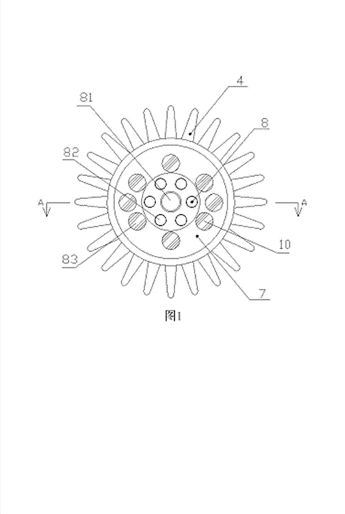
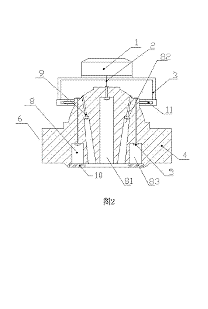
[0021] Such as figure 1 with figure 2 As shown, the high-efficiency heat dissipation high-power LED spotlight includes a bracket 3, a driving power supply 1, a light source wire 2, a radiator 6, and an LED lamp bead 5. The top of the bracket 3 is fixedly connected to the driving power supply 1, and the lower end of the bracket 3 is connected to a slide rail. The ring 12 is symmetrically provided with a sliding shaft 11 on the side wall of the radiator 6, and the sliding shaft 11 is engaged in the slide rail ring 12 to connect the radiator 6 and the bracket 3 together,

[0022] The radiator 6 is composed of a cylindrical base 7 and cooling fins 4. The cooling fins 4 are arranged around the side surface of the base 7. There are fifteen hole-shape...


PUM


Abstract

The invention discloses a high-efficiency radiating high-power LED spot lamp which comprises a bracket (3), a drive power supply (1), a light source wire (2), LED lamp beads (5) and a radiator (6), wherein the radiator (6) consists of a cylindrical basal body (7) and radiating fins (4); a plurality of hole-shaped light source cavities (8) are formed in the center of the basal body (7), and power supply through holes (9) penetrate through the bottoms of the light source cavities to the top of the basal body; and the LED lamp beads (5) are arranged at the bottoms of the light source cavities (8). According to the spot lamp adopting the structure, a radiating structure is arranged, so the spot lamp can adapt to the radiating requirement of high-power working of an LED array and has the advantages of high stability and simple structure and an excellent, more flexible and adjustable light emergent effect.

Description

[0001] technical field [0002] The invention relates to the field of lamps, in particular to a high-power LED spotlight with efficient heat dissipation. [0003] Background technique [0004] Spotlights have the characteristics of high concentration of light. Usually, the angle of irradiation of the emitted beam is less than 30°. It is often used to build modern lighting with no main lights and no fixed scale. It is an important means to create an indoor lighting atmosphere. It has a wide range and various forms. For the application of traditional spotlights, halogen lamps are mostly used, which have disadvantages such as low luminous efficiency, high energy consumption, and short service life. The unidirectionality also forms a perfect support for the light distribution of spotlights, but the traditional spotlight structure is difficult to adapt to the working characteristics of LEDs, especially in terms of heat dissipation. Due to the small power of a single LED and insu...

Claims


Application Information

Patent Timeline
Patent Type & Authority Applications(China)
IPC IPC(8): F21S8/00F21V17/10F21V19/00F21V29/00F21V13/00F21Y101/02F21V29/74
Inventor 陈刚
Owner DUJIANGYAN HUAGANG ELECTRONICS TECH
Learn More