

Support pillar of LED (light emitting diode) backlight module
A backlight module and LED light source technology, which is applied in the field of support columns of direct-type backlight modules, can solve the problems of adding optical films, reducing the overall brightness of LED backlight modules, and increasing the cost of LED backlight modules, so as to eliminate shadows Effect
Inactive Publication Date: 2012-11-07
TPV DISPLAY TECH (XIAMEN) CO LTD
View PDF4 Cites 10 Cited by
- Summary
- Abstract
- Description
- Claims
- Application Information
AI Technical Summary
Problems solved by technology
[0005] 1. Increasing the number of optical films increases the cost of LED backlight modules;
[0006] 2. Increase the number of optical films to reduce the overall brightness of the LED backlight module
Method used
View moreImage
Smart ImageViewing Examples

Examples
Embodiment 1
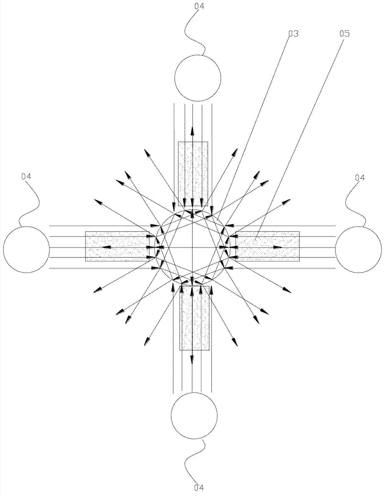
[0034] Such as Figure 4 As shown, the support column 3 is a schematic arrangement position of a quadrangular prism or a prism relative to the LED light source 4 .
Embodiment 2
[0036] Such as Figure 5 As shown, the support column 3 is a hexagonal prism or a truncated prism relative to the schematic arrangement position of the LED light source 4 .
Login to View More PUM
 Abstract
The invention discloses a support pillar of an LED (light emitting diode) backlight module, wherein the support pillar is arranged between a backplane and an optical diaphragm of the LED backlight module; the bottom of the support pillar is fixed on the backplane; a plurality of LED light sources are arranged on the backplane and are distributed like a centre symmetry figure; the support pillar is arranged in the centre of the centre symmetry figure; the support pillar is of a prism structure or prismatic table structure; and the LED light sources are respectively arranged on mid-perpendiculars of bottom borders of the sides of the support pillar. Due to the fact that the LED light sources of the LED backlight module are distributed like the centre symmetry figure, the support pillar is made of a transparent material and arranged in the centre of the centre symmetry figure, and the support pillar is of the prism structure or prismatic table structure, a shadow formed in the LED backlight module by the support pillar is eliminated with lower cost.
Description
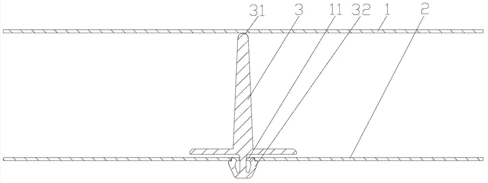
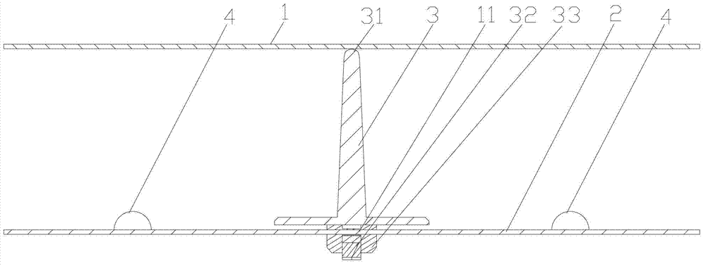
technical field [0001] The invention relates to a support column of a direct-type backlight module in liquid crystal display technology, in particular to a support column of an LED backlight module. Background technique [0002] Liquid crystal display technology has always been used in portable electronic products such as notebook computers, mobile phones, digital cameras, camcorders, and PDAs. In addition to these smaller portable products, the manufacturing technology of large-size liquid crystal panels has also matured recently. For example, desktop LCD monitors have replaced CRT monitors, and LCD TVs are also replacing traditional TVs with their advantages of light weight and clear pictures. The liquid crystal panel is the most critical display element in this field. However, it does not emit light itself, and needs a backlight source to display images. Many backlight technologies exist today, and in large-size liquid crystal display products above 20 inches, direct-li...
Claims
Login to View More Application Information
Patent Timeline
 IPC IPC(8): F21V21/00G02F1/13357F21Y101/02
Inventor林韡林博瑛郑俊义
OwnerTPV DISPLAY TECH (XIAMEN) CO LTD