
Wire tensioning mechanism for automatic wire winding and binding equipment and use method thereof

An automatic winding and equipment technology, applied to the parts of the strapping machine, etc., can solve the problems of difficult maintenance, high maintenance costs, low efficiency, etc., to facilitate automatic winding and bundling operations, low maintenance costs, and use. handy effect

Active Publication Date: 2012-11-14
启东华恩箱包有限公司
View PDF8 Cites 0 Cited by
  • Summary
  • Abstract
  • Description
  • Claims
  • Application Information

AI Technical Summary

Problems solved by technology

In the existing winding and bundling operations, the common operation method is to do the winding and bundling by hand. This kind of operation method is inefficient, and the size and length of the winding and bundling are different, so the bundled products are not beautiful enough, and at the same time , a large number of operators lead to higher production costs
Therefore, various automatic winding and binding equipment have emerged at the historic moment, but in the existing automatic winding and binding equipment, the mechanism setting for fixing the head of the connecting wire is not reasonable enough, or the volume is large, the structure is complicated, and it is not easy to maintain , or the precision is too high, easy to damage, and the cost is high, the maintenance cost is high

Method used


Image

  • Wire tensioning mechanism for automatic wire winding and binding equipment and use method thereof
  • Wire tensioning mechanism for automatic wire winding and binding equipment and use method thereof

Examples


Embodiment

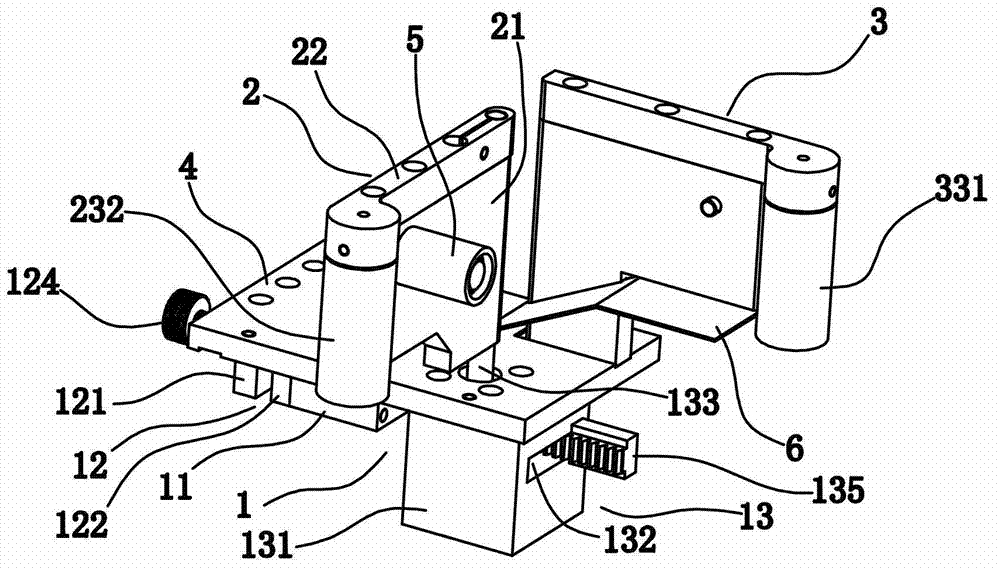
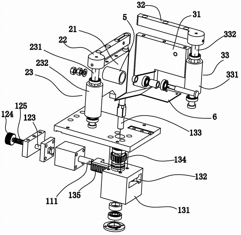
[0024] Example: see figure 1 and figure 2 , the present invention is a wire tensioning mechanism for automatic winding and binding equipment, which includes a power device 1, a movable splint 2 and a certain splint 3, the power device 1 is arranged under a bottom plate 4, and the movable splint 2 is rotatable It is arranged on the bottom plate 4 and connected with the power device 1, the power device 1 drives the movable splint 2 to swing, the fixed splint 3 is fixedly arranged on the bottom plate 4 and corresponds to the movable splint 2, when the movable splint 2 When swinging towards the fixed splint 3 and reaching the set position, the gap formed between the end of the movable splint 2 and the end of the fixed splint 3 will place the connecting wire ends between the movable splint 2 and the fixed splint 3 snapped and secured.

[0025] The power device 1 includes a cylinder 11, an adjustment assembly 12 and a gear assembly 13, the adjustment assembly 12 is connected with...


PUM


Abstract

The invention discloses a wire tensioning mechanism for automatic wire winding and binding equipment, comprising a power device, a movable clamping plate and a fixed clamping plate. The power device is arranged below a bottom plate; the movable clamping plate is rotationally arranged on the bottom plate and connected with the power device; the power device is used for driving the movable clamping device to swing; the fixed clamping plate is arranged on the bottom plate and corresponds to the movable clamping plate; and when the movable clamping plate swings towards the fixed clamping plate and reaches the set position, the head of the connection wire arranged between the movable clamping plate and the fixed clamping plate can be clamped and fixed in the gap formed between the tail end of the movable clamping plate and the tail end of the fixed clamping plate. The invention further discloses a used method of the wire tensioning mechanism for the automatic wire winding and binding equipment. The wire tensioning mechanism for automatic wire winding and binding equipment is simple in structure, reasonable in design and convenient to use, can fix the head of the connection wire automatically to be convenient for wire winding and binding, has low maintenance cost and is worthy of popularization and application.

Description

technical field [0001] The invention relates to wire winding and binding equipment, in particular to a device for automatically winding and binding connecting wires and a method for using the device. Background technique [0002] At present, in the cable production industry with connecting wires such as electric wires and network cables, it is usually necessary to wrap and pack the connecting wires to make the connecting wires have a better shape, which is both beautiful and convenient for transportation. In the existing winding and binding operation, the common operation method is to perform winding and binding by hand, which is inefficient, and the size and length of the winding and binding are different, so the bundled products are not beautiful enough, and at the same time , a large number of operators lead to higher production costs. Therefore, various automated wire winding and binding equipment have emerged at the historic moment, but in the existing automatic windin...

Claims


Application Information

Patent Timeline
Patent Type & Authority Applications(China)
IPC IPC(8): B65B13/18
Inventor 梁首强
Owner 启东华恩箱包有限公司
Learn More