Air control two-way valve

A two-way valve, air control technology, applied in the direction of lift valve, valve details, valve device, etc., can solve the problem of inconvenient installation, and achieve the effect of improving service life and easy installation.

Active Publication Date: 2014-01-08
NINGBO AIRTAC AUTOMATIC INDAL
View PDF6 Cites 0 Cited by
  • Summary
  • Abstract
  • Description
  • Claims
  • Application Information

AI Technical Summary

Problems solved by technology

[0004] The object of the present invention is to provide an air-operated two-way valve with a rotatable control part to solve the problem of inconvenient installation in the background technology

Method used


Image

  • Air control two-way valve
  • Air control two-way valve
  • Air control two-way valve

Examples


Embodiment

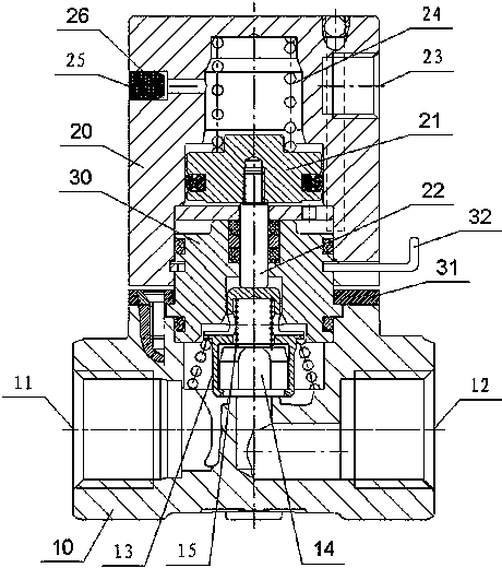
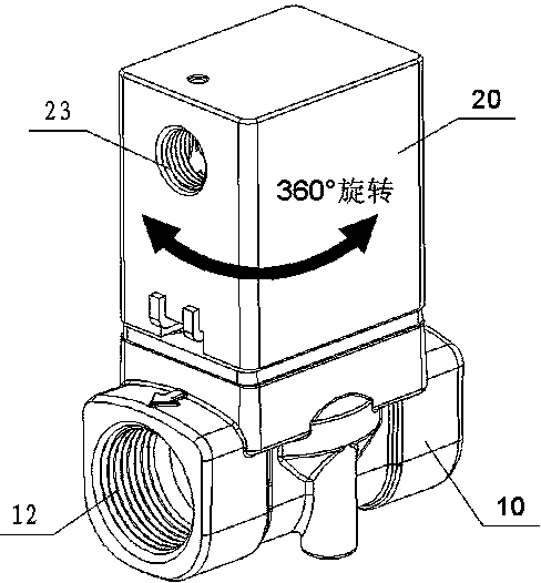
[0022] A pneumatic two-way valve, such as Figures 1 to 3 As shown, the valve body 10 and the cylinder 20 are included, the valve body 10 is provided with a cavity, the cavity is provided with a valve core 13, and the bottom surface of the valve core 13 is provided with a stepped groove with a large outer cavity and a small inner cavity. The outer cavity is covered with a rubber gasket 14, and the inner cavity is provided with a buffer spring 15 that exerts elastic force on the gasket 14. The two outer walls of the valve body 10 are respectively provided with an inlet 11 and an outlet 12 communicating with the cavity, and the outlet 12 The opening at the cavity is facing upward and opposite to the bottom surface of the gasket 14 .

[0023] A slidable piston 21 is provided in the cylinder 20, and the center of the piston 21 is connected with a piston rod 22. The lower end surface of the piston rod 22 is set opposite to the upper end surface of the valve core 13, and an air cont...


PUM


Abstract

Disclosed is a two-way air control valve, comprising a valve body (10) and an air cylinder (20), wherein the valve body (10) is provided with an inlet (11), an outlet (12) and a movable valve core (13); the air cylinder (20) is internally provided with a slidable piston (21); the centre of the piston (21) is connected with a piston rod (22) capable of pressing the valve core (13) to move to open / close a channel arranged between the inlet (11) and the outlet (12); and the outer wall of the air cylinder (20) is provided with an air control interface (23). The two-way air control valve is characterized in that a spacer bush (30) is sheathed between the air cylinder (20) and the piston rod (22), and one side of the spacer bush (30) is fixedly connected to the valve body (10) and the other side of the spacer bush (30) is rotatably connected to the air cylinder (20). The air cylinder portion of the two-way air control valve is rotatable and provides convenience in installation for a client during usage, and the service life of a sealing gasket is prolonged.

Description

technical field [0001] The invention relates to a valve, in particular to an air-controlled two-way valve. Background technique [0002] Air control valves are widely used in food, medicine, industry, washing, petrochemical, metallurgy, spraying, vehicles and other mechanical equipment. [0003] Chinese patent announcement number CN201335155Y discloses a split combined two-position two-way air control valve, including a cylinder and a valve body, a piston is arranged in the cylinder, the center of the piston is connected to a piston rod, and the lower end of the piston rod is provided with The valve core, the side wall of the cylinder is provided with an air control interface, the two ends of the valve body are respectively provided with an inlet joint and an outlet joint, and the channel between the inlet joint and the outlet joint is formed by a valve plate Separated, the inner cavity of the valve between the valve plate and the outlet joint is provided with a horizontal ...

Claims


Application Information

Patent Timeline
Patent Type & Authority Patents(China)
IPC IPC(8): F16K31/122F16K1/36F16K1/46F16K27/02
CPCF16K31/122F16K1/36F16K27/0281F16K31/1221
Inventor 王世忠刘勇陈黎敏王胜旗田文芳
Owner NINGBO AIRTAC AUTOMATIC INDAL
Why Eureka
Try Eureka