Contact finger spring assembly tooling

A technology for assembly tooling and touch fingers, applied in the field of assembly tooling, can solve the problems of increasing use and storage costs, scratching the silver plating layer, time-consuming and labor-intensive problems, etc.

Active Publication Date: 2012-11-14
HENAN PINGGAO ELECTRIC +1
View PDF5 Cites 13 Cited by
  • Summary
  • Abstract
  • Description
  • Claims
  • Application Information

AI Technical Summary

Problems solved by technology

During the installation process, if the contact finger spring cannot be guaranteed to enter the corresponding installation position on the petal-shaped contact finger accurately, workers will use tools to pry the contact finger spring into the installation position, which is not only time-consuming and laborious, but sometimes scratches the silver plating layer
This method can fully meet the production needs when the production batch is small, but when encountering large batches and petal-shaped contacts with different installation diameters, it is a test for the workers' installation skills and labor intensity. Finger springs need to be matched with process devices of different diameters. In practice, due to changes in the dimensions of contacts and electrical connections, there are contact finger springs of various sizes and specifications, and there are also process devices of various specifications, which increases the cost of use and storage.

Method used


Image

  • Contact finger spring assembly tooling
  • Contact finger spring assembly tooling
  • Contact finger spring assembly tooling

Examples


Embodiment Construction

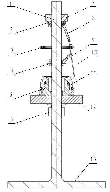
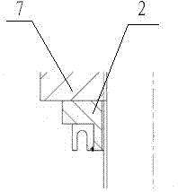
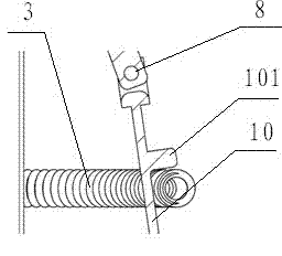
[0016] The embodiment of contact finger spring assembly tooling of the present invention: as figure 1 , figure 2 , image 3 As shown, it includes a fixed platform, a support base 12 and an umbrella rib mechanism. The fixed platform is composed of a base 13 and a screw 1 fixed on the base 13 extending in the up and down direction. The support base 12 is slidably sleeved on the screw 1 It is used to support the contact seat 5 equipped with petal-shaped contact fingers 11. On the screw rod 1, a stop structure 6 is threaded to cooperate with the lower end surface of the support seat 12. The stop structure 6 adopts the internal thread and the screw rod. The nut fitted with the external thread thread can limit the position of the support seat 12 by relying on the stop structure 6, and can adjust the height of the support seat 12 at the same time, and the umbrella rib mechanism is arranged above the support seat. The umbrella bone mechanism includes a guide sleeve 2 which is arran...


PUM


Abstract

The invention discloses a contact finger spring assembly tooling. The contact finger spring assembly tooling comprises a guide rod, the guide rod is matched with a central hole in a contact base in a positioning mode, the guide rod is vertically provided with a guide sleeve and a positioning sleeve, the guide sleeve is sleeved on the guide rod in a sliding mode, the positioning sleeve is fixedly sleeved on the guide rod, pressure rods which are distributed along the circumferential direction of the guide sleeve at intervals are assembled on the guide sleeve in a rotating mode, draw rods are assembled on the positioning sleeve in a rotating mode, support rods are connected between corresponding pressure rods and draw rods, all support rods are matched with each other to form a conical framework used for supporting contact finger springs, corresponding pressure rods, draw rods and support rods are matched with the guide rod to form a four-rod linkage mechanism, the support rods are provided with guiding sections, and each of the guiding sections extends from corresponding draw rod hinge joint position and guides the contact finger springs to the installation position of a petal-shaped contact finger. The contact finger spring assembly tooling has the advantages that the whole tooling is convenient to operate, the installation of the contact finger springs of the petal-shaped contact fingers with different installation diameters is achieved, the contact finger springs are freely slipped to the installation position depending on changes of inclined angle of the support rods, manual shifting is not required, the labor intensity is reduced, and the installation is rapid and accurate.

Description

technical field [0001] The invention relates to the assembly of the petal-shaped contact finger of the circuit breaker with a fixing spring, in particular to an assembly tool. Background technique [0002] In the high-voltage electrical industry, it is generally used to fasten the petal-shaped contact fingers with a ring-shaped spring. The holding force of the contact finger spring is an important guarantee for the close contact between the petal-shaped contact fingers and the conductor. When installing the finger spring on the petal-shaped finger, it is necessary to stretch the finger spring before installing, but in order to ensure the holding force of the finger spring, the stretching allowance of the spring will not be too large, which makes the This installation work becomes very laborious and meticulous. [0003] The installation method commonly used at present is, according to the installation diameter of the finger spring, a conical process device is made to cover t...

Claims


Application Information

Patent Timeline
Patent Type & Authority Applications(China)
IPC IPC(8): H01H69/00
Inventor 杜迎乾林麟李永林王肖斌
Owner HENAN PINGGAO ELECTRIC
Why Eureka
Try Eureka