Method and apparatus of manufacturing piezoelectric vibrating reed, piezoelectric vibration reed, piezoelectric vibrator, oscillator, electronic apparatus and radio-controlled timepiece

A technology of piezoelectric vibrating piece and piezoelectric vibrator, which is applied in the field of radio clocks, can solve problems such as air flow weakening, achieve low cost and reduce manufacturing cost

Inactive Publication Date: 2012-11-14
SEIKO INSTR INC
View PDF1 Cites 2 Cited by
  • Summary
  • Abstract
  • Description
  • Claims
  • Application Information

AI Technical Summary

Problems solved by technology

In addition, in the case of a square wafer, since the distance from the center of rotation to the corner is long, the air flow from the radially inner side to the radially outer side tends to be weakened especially near the corner.

Method used


Image

  • Method and apparatus of manufacturing piezoelectric vibrating reed, piezoelectric vibration reed, piezoelectric vibrator, oscillator, electronic apparatus and radio-controlled timepiece
  • Method and apparatus of manufacturing piezoelectric vibrating reed, piezoelectric vibration reed, piezoelectric vibrator, oscillator, electronic apparatus and radio-controlled timepiece
  • Method and apparatus of manufacturing piezoelectric vibrating reed, piezoelectric vibration reed, piezoelectric vibrator, oscillator, electronic apparatus and radio-controlled timepiece

Examples


Embodiment Construction

[0068] (Piezoelectric vibrating piece)

[0069] First, a piezoelectric vibrating reed according to an embodiment of the present invention will be described with reference to the drawings.

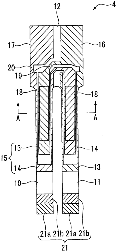
[0070] figure 1 is a plan view of the piezoelectric vibrating piece 4 .

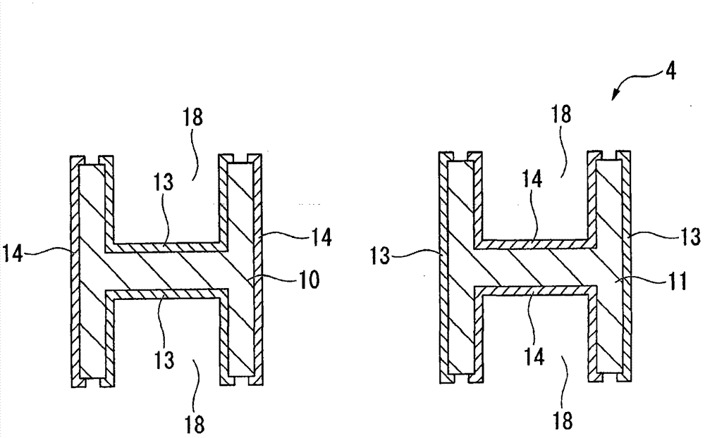
[0071] figure 2 Yes figure 1 The cross-sectional view at the section line A-A.

[0072] like figure 1 As shown, the piezoelectric vibrating piece 4 of this embodiment is a tuning-fork type vibrating piece formed of a square crystal wafer (hereinafter referred to as “square wafer”), and vibrates when a predetermined voltage is applied. The piezoelectric vibrating reed 4 includes: a pair of vibrating arm portions 10, 11 arranged in parallel; a base portion 12 integrally fixing the proximal ends of the pair of vibrating arm portions 10, 11; Vibrating arm grooves 18 on both main surfaces of 11. The vibrating arm groove portion 18 is formed along the longitudinal direction of the vibrating arm portion 10 , 11 fr...


PUM


Abstract

A photoresist film forming process through a spin coating method is included, the photoresist film forming process is performed by rotating a square wafer (65), a spin chuck (70) is provided with a column portion (96), a penetration hole (89a) through which the column portion (96) penetrates is formed in a flow regulating plate (88), a plurality of blowing holes (96) blowing gas toward a second surface (65b) of a square wafer (65) are provided in the upper surface (88a) of the flow regulating plate (88) at the inner side in relation to the outer edge (66) of the square wafer (65) in the radial direction of the wafer maintaining portion (72) and at the outer side in relation to the inner circumferential surface of the penetration hole (89a) in a radial direction of the wafer maintaining portion.

Description

technical field [0001] The present invention relates to a method for manufacturing a piezoelectric vibrating piece, a manufacturing device for a piezoelectric vibrating piece, a piezoelectric vibrating piece, a piezoelectric vibrator, an oscillator, electronic equipment, and a radio clock. Background technique [0002] In recent years, piezoelectric vibrators using crystals (quartz) or the like have been used as time sources, timing sources such as control signals, reference signal sources, and the like in cellular phones and portable information terminal devices. Various types of such piezoelectric vibrators have been provided, and one of them is known as a piezoelectric vibrator having a so-called tuning fork type piezoelectric vibrating piece. The tuning-fork piezoelectric vibrating reed is a sheet-shaped crystal plate, and has a pair of vibrating arms arranged side by side in the width direction; [0003] A specific method of forming the outer shape of the tuning-fork t...

Claims


Application Information

Patent Timeline
Patent Type & Authority Applications(China)
IPC IPC(8): H03H3/02H03H9/02H03H9/19G04C9/02H01L41/22H01L41/311H01L41/313H01L41/332
CPCG04C3/047G04R20/10H03H3/02H03H3/00H03H2003/026H03H9/1021H01L41/332H03H9/21Y10T29/42H10N30/082
Inventor 河口昌之
Owner SEIKO INSTR INC
Why Eureka
Try Eureka