
Multi-core optical fiber discharging device

A multi-core optical fiber, fiber core technology, applied in the field of optical fiber production, can solve the problem of not being able to indicate fiber breakage in time

Inactive Publication Date: 2012-11-21
HENAN COMM CABLE
View PDF6 Cites 5 Cited by
  • Summary
  • Abstract
  • Description
  • Claims
  • Application Information

AI Technical Summary

Problems solved by technology

[0003] The purpose of the present invention is to provide a multi-core optical fiber pay-off device, which is used to automatically monitor the occurrence of fiber breakage, alarm and deal with it in time, so as to solve the problem that the existing fiber pay-off device cannot timely indicate the occurrence of fiber breakage

Method used


Image

  • Multi-core optical fiber discharging device
  • Multi-core optical fiber discharging device
  • Multi-core optical fiber discharging device

Examples


Embodiment 1

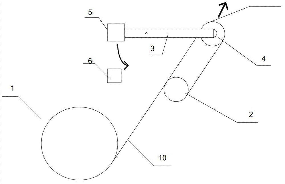
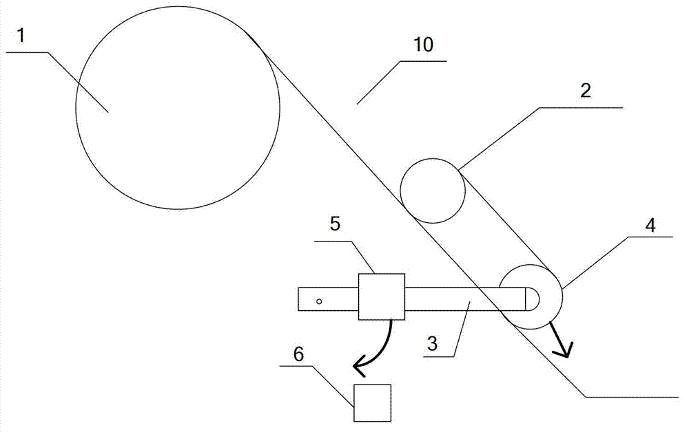
[0020] Such as figure 1 It is a 12-core fiber release device for secondary coated fibers. It is composed of 12 fiber cores to synthesize an optical fiber. Each fiber core comes from a tooth plate, and the number of tooth plates is the same as the number of fiber cores. Such as figure 2 , the crankset 1 is installed on the frame, and each crankset 1 is equipped with a pair of wire passing pulleys on the outlet side, one is the static pulley 2, and the other is the movable pulley 4, and the movable pulley 4 is connected with one to expand the distance between the movable pulley and the static pulley to increase the distance between the movable pulley and the static pulley. Tension device for fiber core tension, the tension device includes a tension swing rod 3 hinged on the frame, one end of the tension swing rod 3 is fixed on the rotating shaft of the movable pulley, and the tension swing rod 3 is connected with a driving tension swing rod to make the movable pulley and the st...


PUM


Abstract

The invention relates to a multi-core optical fiber discharging device. The line outgoing side of each line outgoing mechanism is provided with one pair of line passing wheels; one line passing wheel is a movable pulley (4), and the other line passing wheel is a static pulley (2); the movable pulley is provided with a tension device used for expanding a space between the movable pulley and the static pulley to increase fiber core tension; the tension device comprises a tension oscillating bar (3) hinged to a rack; one end of the tension oscillating bar (3) is fixedly arranged on a spindle of the static pulley; the tension oscillating bar (3) is connected with a tension generating mechanism used for driving the tension oscillating bar to increase the space between the movable pulley and the static pulley; the non-balancing position of the tension oscillating bar on the rack is correspondingly provided with a proximity switch used for monitoring broken fiber generation; the signal output end of the proximity switch is connected with a PLC (programmable logic controller); the output control of the PLC is connected with an alarm device; the proximity switch sends a signal into the PLC; and the PLC outputs an alarm by the alarm device, and prompts to carry out halt processing in time.

Description

technical field [0001] The invention relates to the field of optical fiber production, in particular to a multi-core optical fiber unwinding device and a fiber break protection control system. Background technique [0002] At present, the secondary coated fiber 12-core optical fiber pay-off device does not have a fiber break protection function. It only relies on the operator to patrol the site. If a certain optical fiber is found to be broken, it will be shut down for processing. This method finds problems and processing speed is not timely, and the equipment still operates as usual after the fiber break occurs, so that the produced tube of multi-core loose-packed optical fiber is partially lacking in optical fiber, which affects the length production of the optical cable and causes economic losses to the enterprise. . Contents of the invention [0003] The purpose of the present invention is to provide a multi-core optical fiber pay-off device, which is used to automati...

Claims


Application Information

Patent Timeline
IPC IPC(8): B65H63/024
Inventor 宋广平张辉
Owner HENAN COMM CABLE
Learn More