Lifting appliance for turning cylindrical objects

A cylindrical, object technology, applied in the field of spreaders, can solve problems such as difficult operation

Inactive Publication Date: 2012-11-21
SHANDONG HUALI ELECTRIC MOTOR GRP
View PDF11 Cites 7 Cited by
  • Summary
  • Abstract
  • Description
  • Claims
  • Application Information

AI Technical Summary

Problems solved by technology

[0004] In order to overcome the current technical problem of difficult operation when turning some cylindrical objects, the pre

Method used


Image

  • Lifting appliance for turning cylindrical objects
  • Lifting appliance for turning cylindrical objects
  • Lifting appliance for turning cylindrical objects

Examples


Embodiment Construction

[0014] The present invention will be further described below in conjunction with the accompanying drawings and embodiments.

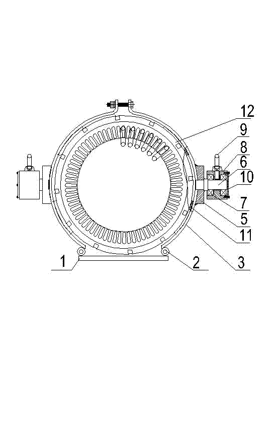
[0015] In this embodiment, the stator of the turning motor is taken as an example to illustrate the structure of the spreader and the action of the spreader turning over a cylindrical object.

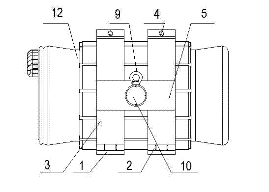
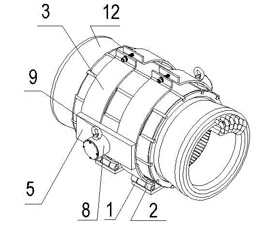
[0016] like figure 1 As shown, a lifting tool for turning cylindrical objects includes a bottom plate 1 for supporting cylindrical objects. The number of bottom plates 1 is reasonably selected according to the length of the cylindrical objects. If the object is short, one bottom plate is Yes, if the object is longer, the number of bottom plates can be appropriately increased. In this embodiment, the number of bottom plates is 2. The number of bottom plates in actual production is preferably 1-3, so as to facilitate the closing and alignment of the tire plates on both sides of the bottom plate as described below.

[0017] like figure 1 As shown, a tire plate 3 ...


PUM


Abstract

The invention relates to a lifting appliance for turning cylindrical objects. In order to overcome the current technical problem that the operation of turning certain cylindrical objects is uneasy. The invention provides the lifting appliance, which comprises at least one bottom plate for supporting a cylindrical object, and the radial width of the bottom plate is less than the diameter of the cylindrical object. The lifting appliance is characterized in that: both side edges of the bottom plate are respectively connected with a curved tire through a hinge, the tires on both sides can be oppositely closed, and the closed ends of the tires are provided with fixed bolt holes; connecting plates are respectively fixed on the outer surfaces of the tires on both sides of the bottom plate, and respectively connect the tires on the same side of each bottom plate together, the connecting plates are provided with supporting shafts, bearings are mounted on the supporting shafts, and hoisting rings are fixed on bearing blocks outside the bearings. The structure of the lifting appliance is simple, the manufacturing cost is low, and the lifting appliance is easy and convenient to operate, is highly applicable, and can effectively solve the problem on how to turn various cylindrical objects.

Description

[0001] technical field [0002] The invention relates to a sling, in particular to a sling capable of turning a cylindrical object freely. Background technique [0003] In the production process, it is often necessary to turn over some cylindrical objects, but there are certain operational troubles when turning over some precision equipment or cylindrical objects that cannot be stressed at both ends. Take the stator in the field of motor production as an example. After the coil is embedded in the stator, the coil joints protrude from both ends of the stator. At this time, if the coil joints are turned over on the operating surface, it is easy to cause deformation and bending of the coil joints at both ends of the stator, and even cause the coil to be damaged. breakage or destruction of the insulation. However, if the stator is fixedly lifted by the lifting rope so that the stator is in a suspended state, although turning over the stator at this time will not cause the two e...

Claims


Application Information

Patent Timeline
IPC IPC(8): B66C1/10B66C13/08
Inventor 郝秦萍王明辉
Owner SHANDONG HUALI ELECTRIC MOTOR GRP
Why Eureka
Try Eureka