
Anti-eccentric-wear roller type valve rocker arm combined device

A valve rocker arm and combined device technology, which is applied in the direction of valve devices, engine components, machines/engines, etc., can solve the front and rear partial wear of valves and valve seat rings, non-fixed contact points between rocker arm pressure heads and valve bridges, and valve failure Complete up and down vertical movement and other issues to achieve uniform valve wear and avoid the effect of valve turnover

Pending Publication Date: 2021-06-15
GUANGXI YUCHAI MASCH CO LTD
View PDF0 Cites 1 Cited by
  • Summary
  • Abstract
  • Description
  • Claims
  • Application Information

AI Technical Summary

Problems solved by technology

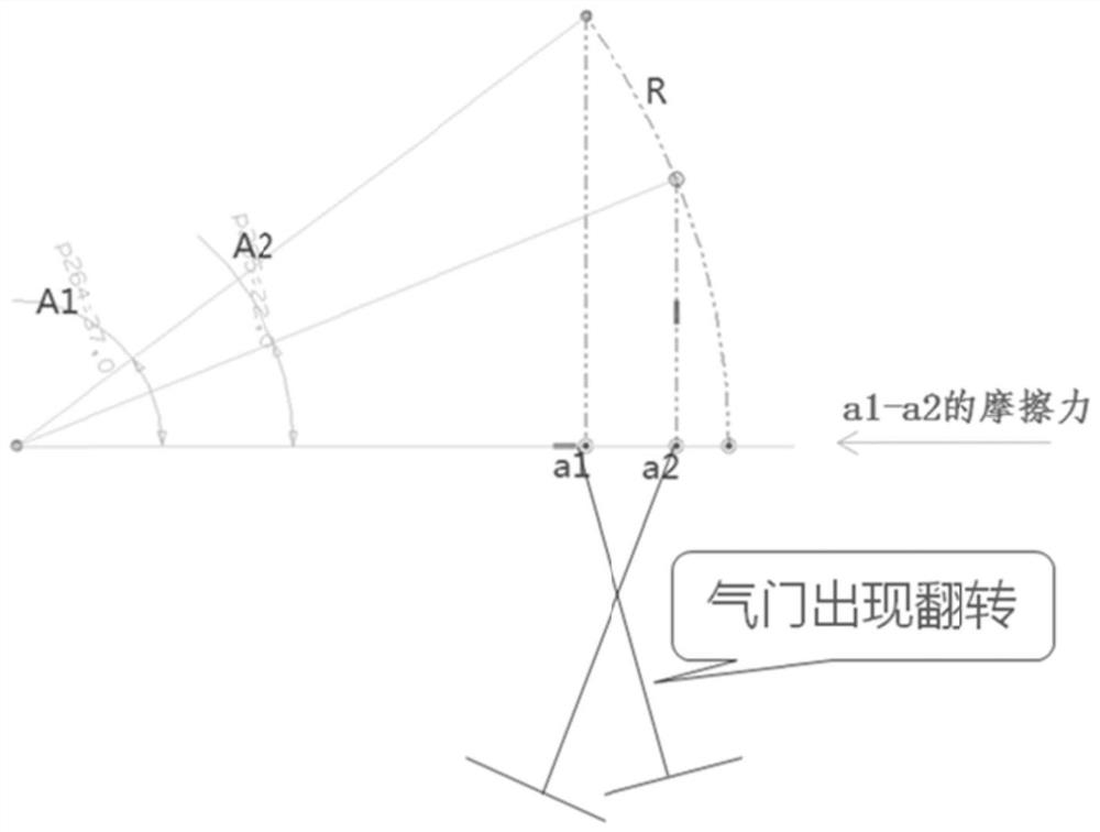
[0003] The valve rocker arm combination device of the prior art has the following disadvantages: since the valve rocker arm is centered on the rocker arm axis, the rocker arm is a tangent up and down movement with the radius R, that is, a non-vertical up and down motion, causing the rocker arm pressure head and The contact points of the valve bridge are not fixed
like image 3 As shown, when the rocker arm angles are A1 and A2, the contact point between the pressure head and the valve bridge will have a distance of a1-a2. The throwing force further acts on the valve stem, causing the valve not to be fully vertically stressed, but also being dragged forward and backward by the valve bridge, which eventually causes the valve to not move vertically up and down completely, causing the valve and the valve seat ring to deviate back and forth. Grind badly

Method used


Image

  • Anti-eccentric-wear roller type valve rocker arm combined device
  • Anti-eccentric-wear roller type valve rocker arm combined device
  • Anti-eccentric-wear roller type valve rocker arm combined device

Examples


Embodiment Construction

[0018] The specific embodiments of the present invention will be described in detail below in conjunction with the accompanying drawings, but it should be understood that the protection scope of the present invention is not limited by the specific embodiments.

[0019] Unless expressly stated otherwise, throughout the specification and claims, the term "comprise" or variations thereof such as "includes" or "includes" and the like will be understood to include the stated elements or constituents, and not Other elements or other components are not excluded.

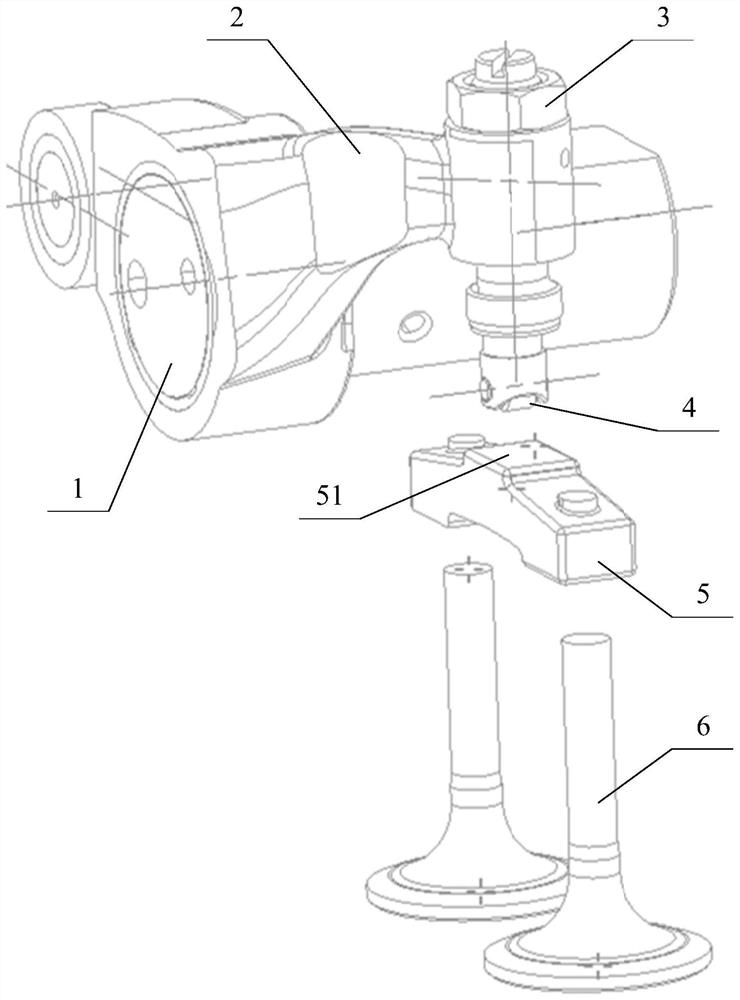
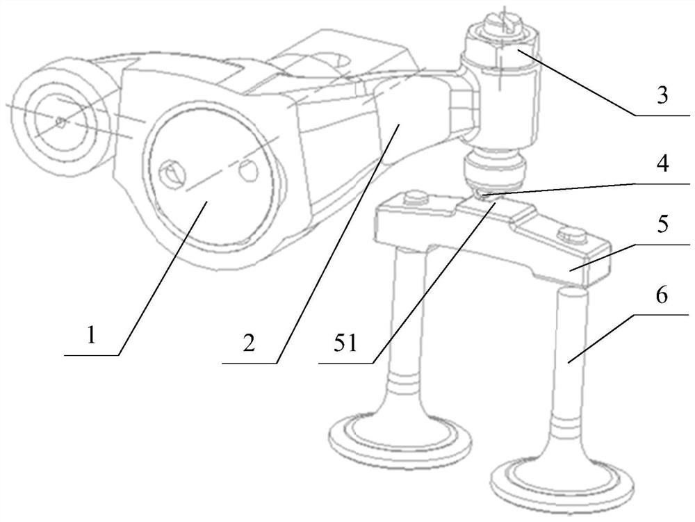
[0020] like Figure 1 to Figure 2 As shown, an anti-eccentric roller valve rocker arm combination device according to a preferred embodiment of the present invention includes a valve rocker shaft 1, a valve rocker arm 2, a valve adjustment screw 3, a roller 4, a valve bridge 5 and a valve 6 .

[0021] see Figure 1 to Figure 2 , in some embodiments, the valve rocker shaft 1 can rotate around the circumference of the valv...


PUM


Abstract

The invention discloses an anti-eccentric-wear roller type valve rocker arm combined device which comprises a valve rocker arm shaft, a valve rocker arm, a valve adjusting screw and a roller. The valve rocker arm shaft can rotate with the circumferential line of the valve rocker arm shaft as the axis. The valve rocker arm is arranged on the valve rocker arm shaft, extends in the radial direction of the valve rocker arm shaft in the direction away from the central axis of the valve rocker arm shaft and can swing along with the valve rocker arm shaft with the circumferential line of the valve rocker arm shaft as the axis and the length of the valve rocker arm as the radius. The valve adjusting screw is arranged on the valve rocker arm, and the valve rocker arm can drive the valve adjusting screw to swing together. The roller is arranged at the lower end of the valve adjusting screw and can move along with the valve adjusting screw. The anti-eccentric-wear roller type valve rocker arm combined device can solve the problems of eccentric wear and overturning of a valve.

Description

technical field [0001] The invention relates to the field of valve rocker arm combination devices, in particular to a roller type valve rocker arm combination device for preventing partial wear. Background technique [0002] The prior art valve rocker combination device such as image 3 As shown, the valve rocker arm is in contact with the valve bridge by a pressure head with a universal joint, and the contact surface of the valve bridge is flat. The valve rocker arm moves up and down, and the valve bridge also moves up and down with the valve rocker arm pressure head, and the valve bridge drives the valve to move up and down, thereby realizing the switch of the valve. [0003] The valve rocker arm combination device of the prior art has the following disadvantages: since the valve rocker arm is centered on the rocker arm axis, the rocker arm is a tangent up and down movement with the radius R, that is, a non-vertical up and down motion, causing the rocker arm pressure head ...

Claims


Application Information

Patent Timeline
IPC IPC(8): F01L1/26F01L1/18
CPCF01L1/181F01L1/26
Inventor 韦良锦黄永全
Owner GUANGXI YUCHAI MASCH CO LTD
Learn More