Proportional electromagnet for controlling position of valve core of hydraulic valve

A proportional electromagnet and spool position technology, applied in the field of electromagnets, can solve problems such as unstable mechanical output force, unstable oil flow rate, and unbalanced oil pressure, so as to achieve stable changes in mechanical output force and stable hydraulic equipment Work and hydraulic pressure changes smoothly

Active Publication Date: 2012-11-21
宁波市鄞州通力液压电器厂
View PDF4 Cites 8 Cited by
  • Summary
  • Abstract
  • Description
  • Claims
  • Application Information

AI Technical Summary

Problems solved by technology

When this proportional electromagnet is used to control the position of the hydraulic valve spool, since the oil in the second cavity and the third cavity are connected through the hydraulic damping hole, the oil pressure on the upper end surface and the lower end surface of the armature is balanced. At the same time, because the push rod is solid, the lower end surface of the push rod receives the oil pressure in the spool chamber of the hydraulic valve and the upper end surface of the push rod receives the oil pressure in the first cavity, so the overall oil hydraulic pressure received by the armature assembly The force is unbalanced, thereby forming a hydraulic disturbance to the armature assembly, and the output force of the armatu

Method used


Image

  • Proportional electromagnet for controlling position of valve core of hydraulic valve
  • Proportional electromagnet for controlling position of valve core of hydraulic valve

Examples


Embodiment Construction

[0023] The present invention will be further described in detail below in conjunction with the accompanying drawings and embodiments.

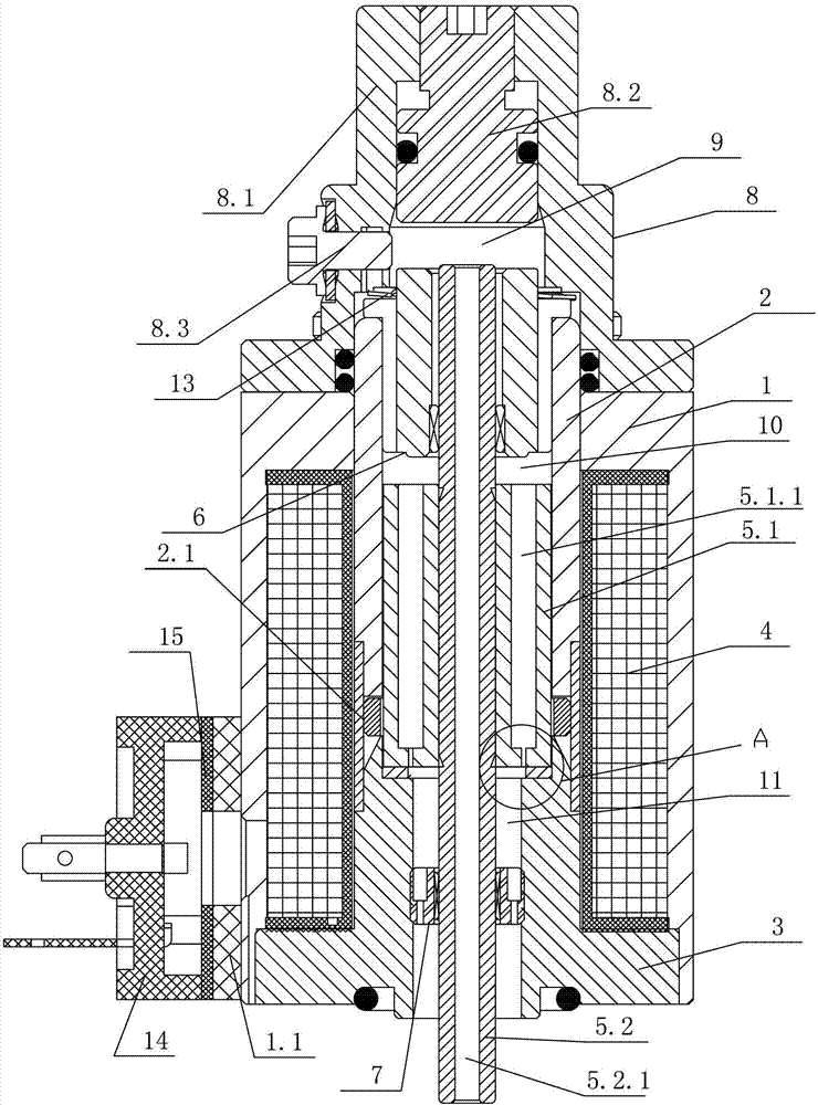
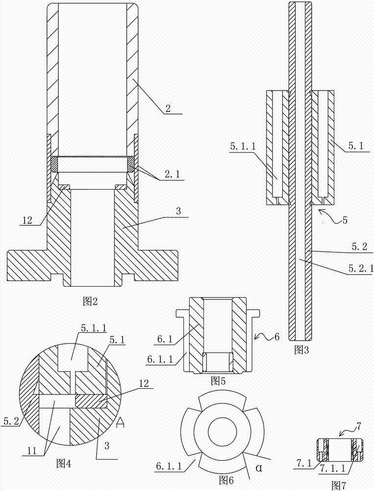
[0024] Such as figure 1 As shown, a proportional electromagnet used to control the position of the spool of a hydraulic valve includes an electromagnetic induction assembly and an armature assembly 5. As an improvement, the electromagnetic induction assembly includes a housing 1, a magnetic guide tube 2, a magnetic shoe 3, and a coil assembly 4 and an end cap assembly 8 provided with stepped holes; as figure 2 As shown, the magnetic tube 2 and the magnetic shoe 3 are welded into a whole through the non-magnetic material 2.1, and the magnetic tube 2 and the magnetic shoe 3 cooperate to form an inner cavity, so that the inner cavity has sufficient compressive strength; the shell 1, the magnetic The tube 2 and the magnetic shoe 3 form a chamber, and the coil assembly 4 is arranged in the chamber, and the chamber is filled with a plastic sealing...


PUM

PropertyMeasurementUnit
Angleaaaaaaaaaa

Abstract

The invention discloses a proportional electromagnet for controlling a position of a valve core of a hydraulic valve. The proportional electromagnet comprises an electromagneticinduction component and an armature component, wherein the armature component is arranged in the electromagneticinduction component and is in sliding fit with the electromagneticinduction component; the proportional electromagnet is also provided with a hydraulic passage which is communicated with an upper end face and a lower end face of the armature component and forms a hydraulic loop with a valve core cavity of the hydraulic valve; a hydraulic loop is formed between the upper end face as well as the lower end face of the armature component and the valve core cavity of thehydraulic valve, so that the upper end face as well as the lower end face of the armature component and the valve core cavity of thehydraulic valve are hydraulically balanced, hydraulic disturbance is effectively eliminated, the output power of the proportional electromagnet is stably output, and the positional relation of the valve core and a valve seat of the hydraulic valve is effectively controlled; and thus, the flow velocity of oil in the hydraulic valve is controlled, the hydraulic pressure of the oil in an executing element of the hydraulic system is stably adjusted, and the hydraulic equipment stably works.

Description

technical field [0001] The invention relates to an electromagnet, in particular to a proportional electromagnet for controlling the position of a valve core of a hydraulic valve. Background technique [0002] Large-scale hydraulic equipment such as injection molding machines, excavators, and cranes require the use of hydraulic systems, which consist of power components, actuators, control components, auxiliary components and hydraulic oil. The basic working principle of the hydraulic system is: after the hydraulic oil is boosted or depressurized by the power element, it flows into the control element, and after being controlled by the control element, it is input into the actuator in a smooth and orderly manner, and the actuator converts hydraulic energy into mechanical energy. output. The control element is usually a proportional hydraulic valve, and the proportional hydraulic valve is formed by assembling a hydraulic valve and a proportional electromagnet. Proportional e...

Claims


Application Information

Patent Timeline
IPC IPC(8): F16K31/06
Inventor 刘晓林陈华林陈晓齐
Owner 宁波市鄞州通力液压电器厂
Why Eureka
Try Eureka