Pushbutton structure

A technology of limiting part and chute, applied in the field of push button structure, can solve problems such as hidden dangers of safety and normal use, damage to the state of mutual conflict, poor reliability of push button structure, etc.

Inactive Publication Date: 2012-11-21
NINGBO HANPU TOOLS
View PDF12 Cites 0 Cited by
  • Summary
  • Abstract
  • Description
  • Claims
  • Application Information

AI Technical Summary

Problems solved by technology

[0002] The current push button structure includes a push block and a chute. The push block cooperates with the chute and the two can slide relative to each other. There are protrusions, and the two protrusions on the same side of the push block and the slide groove can interfere with each other, and at least one of the two protrusions has elasticity, so that when pushing the push block, it is necessary to apply a larger force to overcome The elasticity of the elastic protrusions ...

Method used


Image

  • Pushbutton structure
  • Pushbutton structure

Examples


Embodiment Construction

[0015] The present invention will be further described below in conjunction with the drawings.

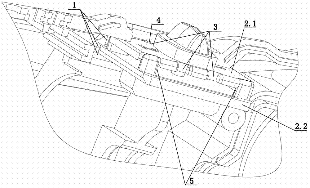
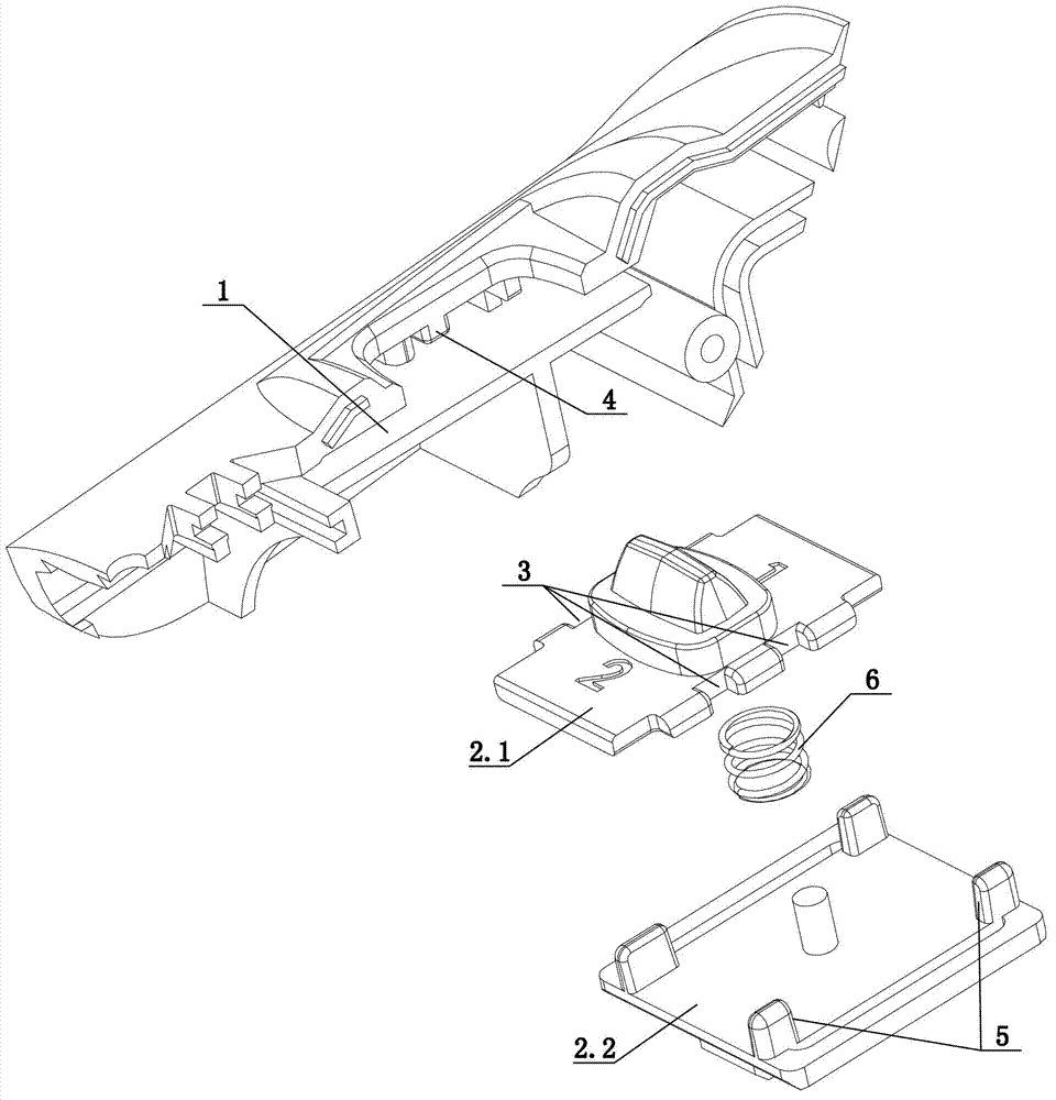
[0016] The push button structure of the present invention includes a push block and a sliding groove 1, and the push block cooperates with the sliding groove 1 and can slide relative to each other. The push block includes a first part 2.1 and a second part 2.2 that can move up and down relative to each other; The first part 2.1 is provided with at least two first limiting parts 3 in sequence along the sliding direction, and the sliding groove 1 is provided with any one of the first limiting parts 3 to limit the first part 2.1. The second limiting portion 4 slides along the sliding direction; when the first portion 2.1 moves upward relative to the second portion 2.2, the first limiting portion 3 is connected to the second limiting portion 4, and the first portion 2.1 is relative to the second When the part 2.2 moves downwards, the first limiting portion 3 and the second limiting portio...


PUM


Abstract

The invention discloses a pushbutton structure which has good reliability. The pushbutton structure comprises a push block and a sliding chute (1), wherein the push block and the sliding chute (1) are cooperated and can slide relatively, the push block comprises a first part (2.1) and a second part (2.2) which can move up and down relatively; the first part (2.1) is sequentially provided with at least two first position limiting parts (3) along the sliding direction, and the sliding chute (1) is provided with a second position limiting part (4) which can be connected with one of the first position limiting parts (3) to limit the first part (2.1) to slide along the sliding direction; when the first part (2.1) is moved upwards relative to the second part (2.2), the first position limiting parts (3) and the second position limiting part (4) are connected, and when the first part (2.1) is moved downwards relative to the second part (2.2), the first position limiting parts (3) and the second position limiting part (4) are separated.

Description

Technical field [0001] The invention relates to the technical field of push button structures, in particular to a push button structure. Background technique [0002] The current push button structure includes a push block and a sliding groove. The push block cooperates with the sliding groove and can slide relative to each other. In order to have a certain resistance limit on the push block, the push block and the sliding groove are provided on both sides of the sliding direction. There are protrusions, the two protrusions on the same side of the push block and the sliding groove can interfere with each other, and at least one of the two protrusions has elasticity. In this way, when the push block is pushed, a greater force needs to be applied to overcome The elasticity of the elastic protrusions, thereby destroying the conflicting state, enables the push block to move along the chute. Although the above-mentioned structure simply achieves the design requirements for resistance ...

Claims


Application Information

Patent Timeline
IPC IPC(8): H01H3/20
Inventor 陈会甫
Owner NINGBO HANPU TOOLS
Why Eureka
Try Eureka