Assembling jig for antenna casing

A technology for assembling jigs and housings, which is applied to antennas, antenna supports/mounting devices, antenna components, etc. It can solve the problems of glue overflow on antenna housings, difficult assembly, uneven gaps, etc., and achieve simple assembly, Easy to operate, uniform gap effect

Inactive Publication Date: 2012-11-21
SHENZHEN FUTAIHONG PRECISION IND CO LTD
View PDF4 Cites 8 Cited by
  • Summary
  • Abstract
  • Description
  • Claims
  • Application Information

AI Technical Summary

Problems solved by technology

However, it is easy to cause the glue on the antenna shell to overflow by manual operation, and there will be uneven gaps after assembly, the assembly is difficult, and the yield of the assembled product is low

Method used


Image

  • Assembling jig for antenna casing
  • Assembling jig for antenna casing
  • Assembling jig for antenna casing

Examples


Embodiment Construction

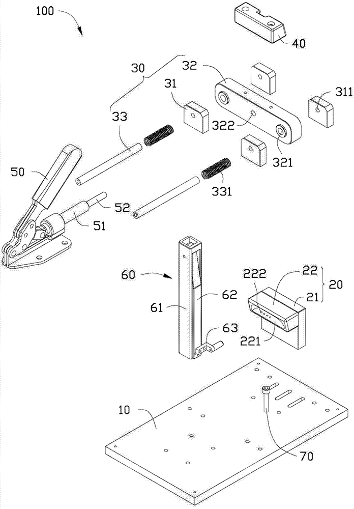
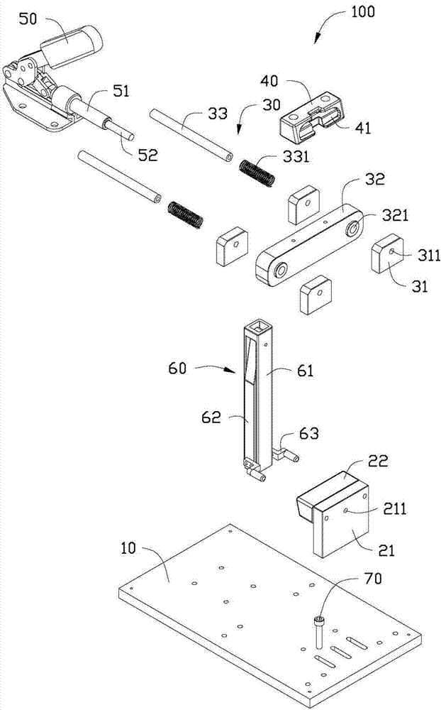
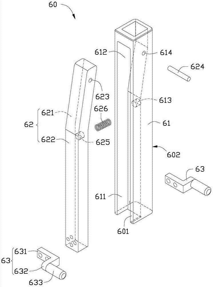
[0016] Please also refer to figure 1 and figure 2 , the preferred embodiment of the present invention provides a portable electronic device antenna housing assembly jig 100, including a base 10, a first mounting part 20, a sliding part 30, a second mounting part 40, an operating part 50 and a clamping part 60 .

[0017] The base 10 is a rectangular plate. The first mounting member 20 includes a fixing plate 21 and a mounting portion 22 . The fixing plate 21 is substantially in the shape of a rectangular plate, and is fixed on the base 10 . The mounting portion 22 is roughly block-shaped and fixed on one side of the fixing plate 21 . A first mounting slot 221 is defined on a side of the mounting portion 22 away from the fixing plate 21 . The shape and structure of the first installation groove 221 correspond to the shape and structure of the existing antenna housing, and are used for accommodating the antenna housing. An air suction hole 222 is defined in the first insta...


PUM


Abstract

An assembling jig for an antenna casing is used for assembling a connecting piece on the antenna casing and comprises a base, a first installing piece, a sliding piece and a second installing piece. The first installing piece is fixed on the base, and a first installing groove is arranged on the first installing piece and used for installing the antenna casing. The sliding piece comprises a plurality of positioning plates, a sliding part and at least one guide pillar. By enabling the guide pillar to respectively penetrate through the positioning plates and the sliding part, the sliding part is sleeved on the guide pillar and can slide along the guide pillar, and the second installing piece is arranged on the sliding part and is opposite to the first installing piece. A second installing groove is arranged on the second installing piece and used for installing the connecting piece. By operating the sliding part, the sliding part can slide along the guide pillar, so that the connecting piece is driven to move towards the antenna casing, and the connecting piece is installed on the antenna casing.

Description

technical field [0001] The invention relates to an assembly fixture, in particular to an antenna shell assembly fixture. Background technique [0002] During the assembly process between the antenna housing of the portable electronic device and the body of the portable electronic device, it is generally necessary to install a substantially ring-shaped connector between the antenna housing and the body of the portable electronic device to fill the antenna housing The gap between it and the body of the portable electronic device, and plays a decorative role. The specific assembly method is as follows: dispensing glue on the antenna shell, and then manually installing the connecting piece on the antenna shell. However, it is easy to cause the glue on the antenna housing to overflow by manual operation, and the phenomenon of uneven gap after assembly occurs, the assembly difficulty is relatively high, and the yield rate of the assembled product is low. Contents of the inventi...

Claims


Application Information

Patent Timeline
Patent Type & Authority Applications(China)
IPC IPC(8): H01Q1/22H01Q1/42
CPCH01Q1/243Y10T29/53961
Inventor 王新艳
Owner SHENZHEN FUTAIHONG PRECISION IND CO LTD
Why Eureka
Try Eureka