End cap modification device

A technology of end cap and drive device, applied in the field of component processing, to achieve the effect of the same height, the same bevel angle and simple structure

Inactive Publication Date: 2015-11-11
CRRC BEIJING ERQI LOCOMOTIVE CO LTD
View PDF3 Cites 0 Cited by
  • Summary
  • Abstract
  • Description
  • Claims
  • Application Information

AI Technical Summary

Problems solved by technology

[0005] The object of the present invention is to propose a device for modifying end caps to achieve the advantages of high efficiency and good precision in modifying the end caps.

Method used


Image

  • End cap modification device
  • End cap modification device
  • End cap modification device

Examples


Embodiment 1

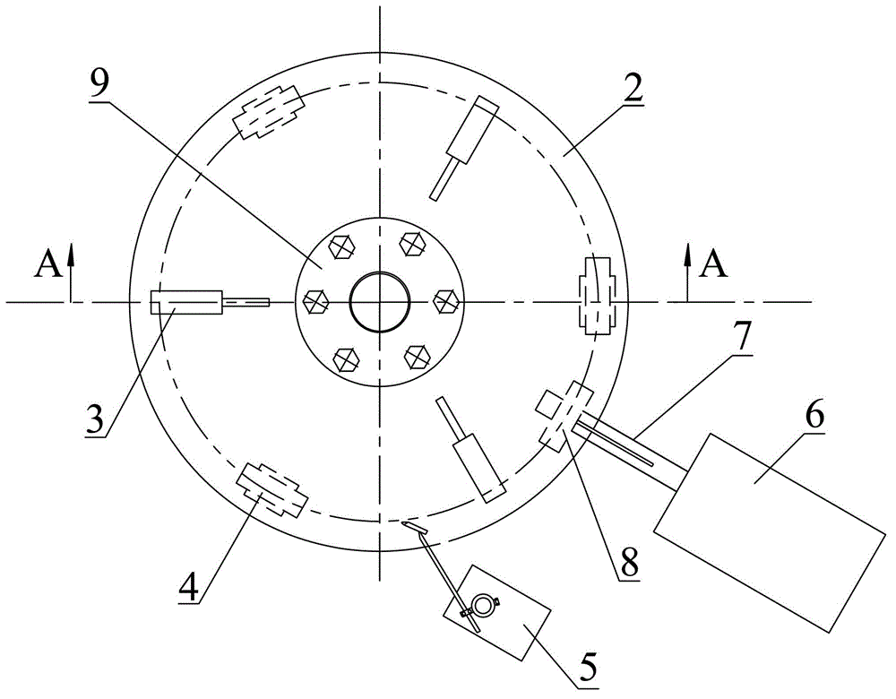
[0026] image 3 It is a top view of the end cap modification device of the present invention; Figure 4 for image 3 AA sectional view of ; Figure 5 It is a schematic diagram of the connection between the connecting shaft and the driving wheel; Figure 6 Schematic diagram of the height adjustment device.

[0027] This embodiment provides a device for modifying end caps, such as image 3 and Figure 4 As shown, it includes a turntable 2, a limit post 10, a support post 12, a torch support 5 and a driving device.

[0028] The turntable 2 used in this embodiment is a ring-shaped metal disk, and the top of the turntable 2 is provided with a support for fixing the end cover that matches the end cover; A support block 3 matched with the outer edge of the end cover.

[0029] The center of the turntable 2 is pierced with a limit pillar 10, and the inner ring of the turntable 2 close to the limit pillar 10 is provided with a bearing 11; the position above the turntable 2 close ...


PUM


Abstract

The invention provides a shaping device of an end cover. The shaping device comprises a rotary disc, a limiting supporting column, supporting columns, a cutting torch bracket and a driving device, wherein the rotary disc is a ring-shaped rotary disc; a supporting seat matched with the end cover is arranged above the rotary disc; the limiting supporting column is arranged at the center of the rotary disc in a penetrating manner; the inner ring of the rotary disc, which is close to the limiting supporting column, is provided with a bearing; the supporting column is arranged under the rotary disc, one end of the supporting column contacted with the rotary disc is provided with a roller, and the rotating shaft of the roller is radially arranged along the rotary disc; the driving device comprises a motor and a driving wheel; the output shaft of the motor is radially arranged and is coaxially connected with the driving wheel, and the driving wheel is positioned under the rotary disc and is contacted with the disc surface of the rotary disc; the cutting torch bracket is fixed at the outer side of the rotary disc and is provided with a clamp for fixing the cutting torch and a height adjusting device; and the clamp is fixed on the height adjusting device. The shaping device provided by the invention has the advantages that the defects of the existing manual shaping are overcome, and the advantages of high shaping efficiency and excellent shaping accuracy of the end cover are realized.

Description

technical field [0001] The invention relates to element processing technology, in particular to an end cap modification device. Background technique [0002] The manufacturing method of the existing main air cylinder end cover of diesel locomotive is as follows: first, hot-rolled steel plate is used to stamp and form the initial end cover by hydraulic press; then the initial end cover is modified to meet the requirements of the end cover design drawings. At present, the modification of the initial product of the end cap adopts manual operation. The operator holds the cutting torch and uses the oxyacetylene flame to correct the height and shape of the initial product of the end cap so that it meets the size requirements of the end cap design drawing. figure 1 Schematic diagram of the structure of the end cap. [0003] At present, the end cap modification technology is to place the initial end cap on the working platform, measure its height and draw a line in advance, and det...

Claims


Application Information

Patent Timeline
Patent Type & Authority Patents(China)
IPC IPC(8): B23K7/00B23K7/10
Inventor 王亚玲
Owner CRRC BEIJING ERQI LOCOMOTIVE CO LTD
Why Eureka
Try Eureka