Feed shaft thermal deflection compensating method of comprehensive machining machine

A technology of comprehensive processing and compensation methods, applied in metal processing mechanical parts, metal processing, metal processing equipment and other directions, can solve problems such as bed errors, and achieve the effect of correcting thermal displacement errors

Active Publication Date: 2012-11-28
PRECISION MACHINERY RES & DEV CENT
View PDF9 Cites 6 Cited by
  • Summary
  • Abstract
  • Description
  • Claims
  • Application Information

AI Technical Summary

Problems solved by technology

[0003] However, since the thermal deformation of the feed shaft is not the same in different parts, the thermal deformation displacement measured only from the tail end of the feed shaft is not equal to the thermal displacement error of the bed, so that the The bed platform still has a considerable error after compensation

Method used


Image

  • Feed shaft thermal deflection compensating method of comprehensive machining machine
  • Feed shaft thermal deflection compensating method of comprehensive machining machine
  • Feed shaft thermal deflection compensating method of comprehensive machining machine

Examples


Embodiment Construction

[0030] The present invention will be described in detail below in conjunction with the accompanying drawings and embodiments.

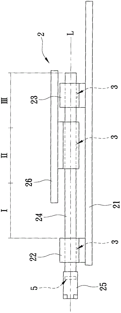
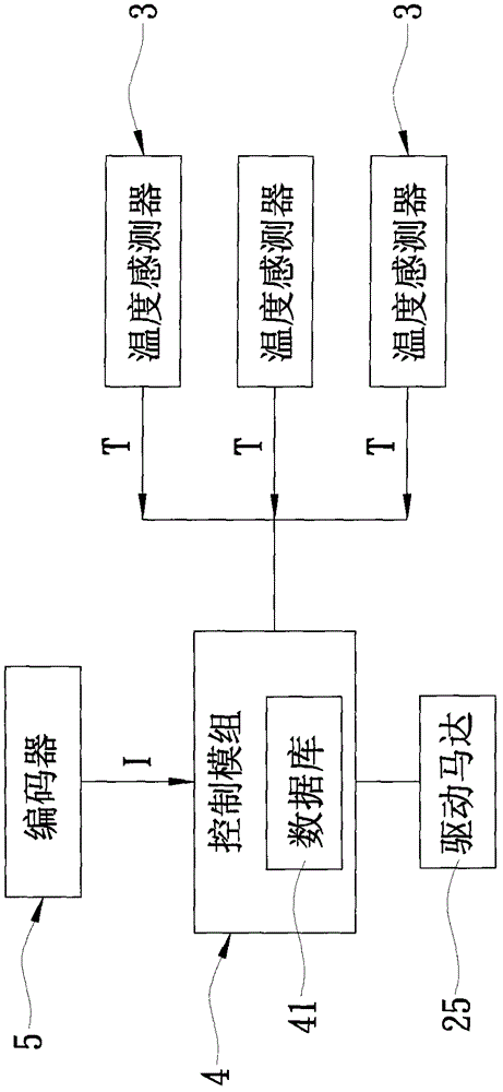
[0031] refer to figure 1 , 2 , 3, a preferred embodiment of the feed shaft thermal displacement compensation method of the comprehensive processing machine of the present invention is applied to a comprehensive processing machine 2, the comprehensive processing machine 2 includes a machine base 21, a machine seat arranged on the machine base 21 The drive bearing seat 22, a support bearing seat 23 arranged on the machine base 21 and spaced apart from the drive bearing seat 22, and a support bearing seat 23 rotatably passing through the drive bearing seat 22 and the support bearing seat 23 along an axis L The feed shaft 24 , a drive motor 25 connected to drive the feed shaft 24 to rotate, and a bed 26 mounted on the feed shaft 24 and moving along the axis L as the feed shaft 24 rotates.

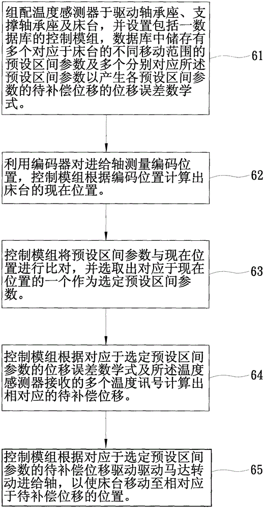
[0032] The compensation method includes the following steps 61 ...


PUM


Abstract

The invention discloses a feed shaft thermal deflection compensating method of a comprehensive machining machine. The compensating method is applied to a comprehensive machining machine which comprises a feed shaft and a platform installed on the feed shaft. The compensating method comprises the following steps: assembling a plurality of temperature sensors on the comprehensive machining machine; arranging a control module which is electrically connected with the temperature sensors and comprises a databank, wherein a plurality of preset region parameters corresponding to different movement ranges, and a plurality of displacement error mathematic expressions (corresponding to the preset region parameters) of displacement to be compensated, are stored inside the databank; measuring the feed shaft according to an encoder so as to calculate out the position of the platform by virtue of the control module and selecting one preset region parameter corresponding to the position; subsequently calculating out the displacement to be compensated according to the displacement error mathematic expressions and a plurality of received temperature signals; and moving the platform to a corresponding position, thereby reducing the error caused by the thermal deflection.

Description

technical field [0001] The invention relates to a processing machine, in particular to a feed shaft of a comprehensive processing machine. Background technique [0002] An existing feed shaft thermal displacement compensation method for a processing machine, as shown in Taiwan Patent No. M358692, is applied to a processing machine, which has a rotatable feed shaft, and a mounted and supported The bed that is driven and moved by the feed shaft, the compensation method is to install a displacement sensor at the end of the feed shaft, and use the displacement sensor to measure the heat generated at the end of the feed shaft during processing. thermal deformation displacement, and then drive the feed shaft to rotate to move the bed to eliminate the thermal deformation displacement, thereby achieving the beneficial effect of correcting the thermal displacement error suffered by the bed. [0003] However, since the thermal deformation of the feed shaft is not the same in differen...

Claims


Application Information

Patent Timeline
Patent Type & Authority Applications(China)
IPC IPC(8): B23Q15/12
Inventor 苏春维廖茂钦
Owner PRECISION MACHINERY RES & DEV CENT
Why Eureka
Try Eureka