Thermoelectric device and mirror surface state detection device

Inactive Publication Date: 2005-10-06
YAMATAKE HONEYWELL CO LTD
View PDF1 Cites 34 Cited by
  • Summary
  • Abstract
  • Description
  • Claims
  • Application Information

AI Technical Summary

Benefits of technology

[0014] The present invention has been made to solve the above-described problems, and has as its object to provide a ther

Problems solved by technology

However, for the above-described conventional mirror surface cooling dew point detector 101 or 102, assembly is not easy because the temperature detection element 6 is embedded through the silicone grease in the hole formed in the side portion of the copper block 3.
Since the temperature detection element 6 is covered with the silicone grease, the response is poor due to the thermal resistance by the silicone grease.
In addition, since the thermal capacity by the co

Method used


Image

  • Thermoelectric device and mirror surface state detection device
  • Thermoelectric device and mirror surface state detection device
  • Thermoelectric device and mirror surface state detection device

Examples


Example

First Embodiment: Mirror Surface Cooling Dew Point Detector (Scattered Light Detection Method)

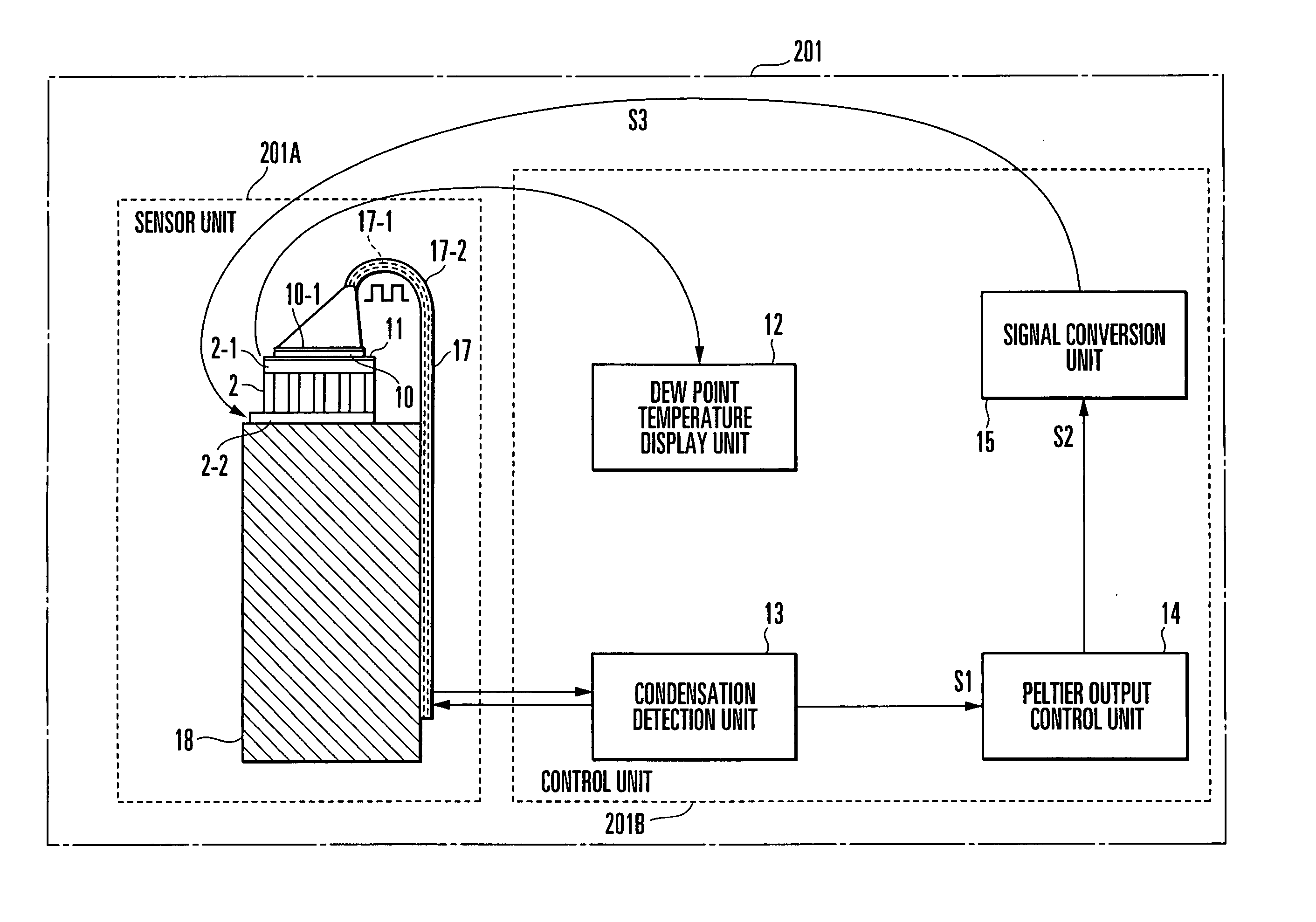
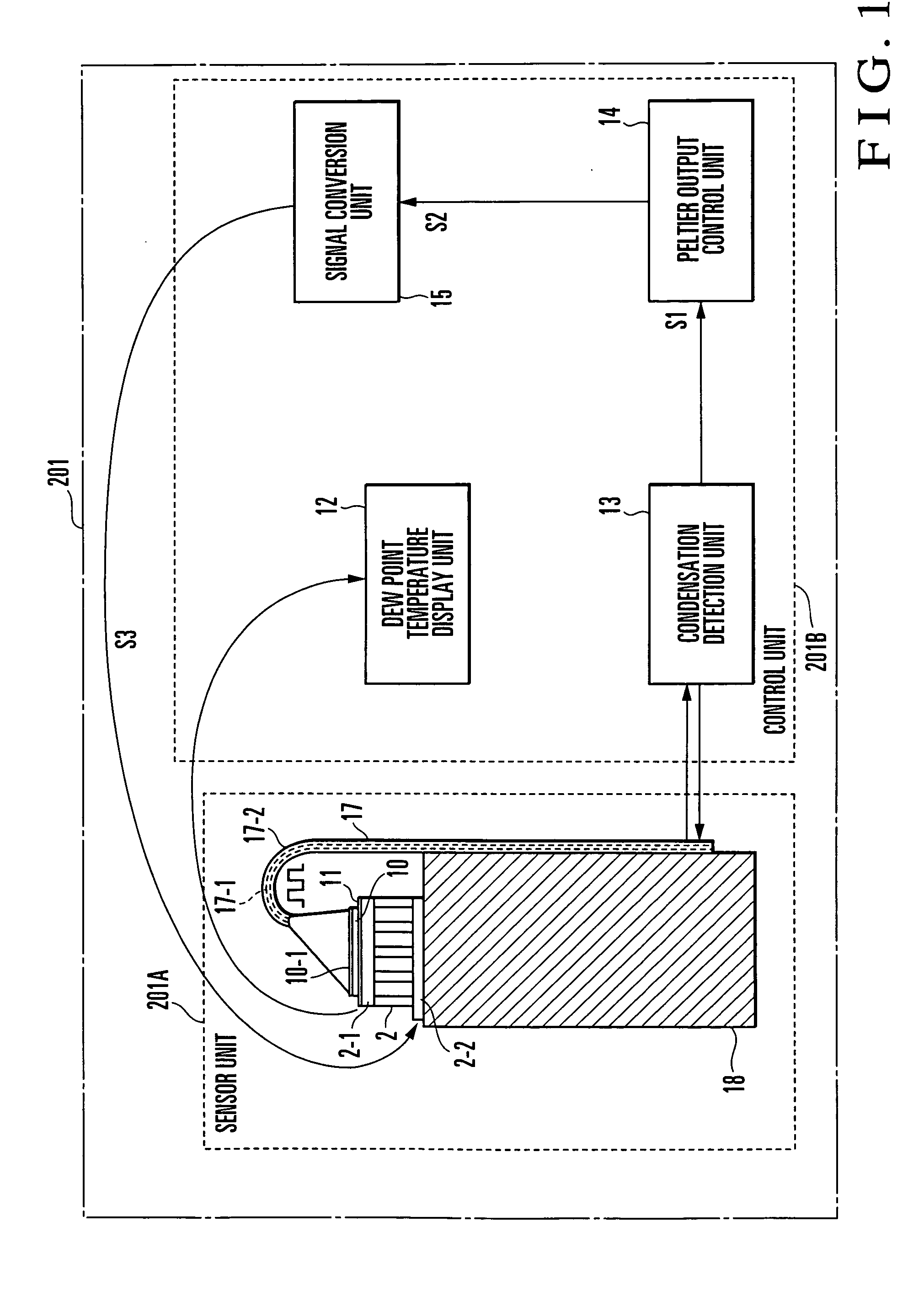
[0056]FIG. 1 shows an embodiment of a mirror surface cooling dew point detector which uses a thermoelectric device according to the present invention. A mirror surface cooling dew point detector 201 has a sensor unit 201A and control unit 201B.

[0057] In the sensor unit 201A, a mirror 10 is attached to a cooled surface 2-1 of a thermoelectric cooling element (Peltier element) 2. The mirror 10 is formed from, e.g., a silicon chip whose surface 10-1 is a mirror surface. A thin-film resistance thermometer sensor (temperature detection element) 11 made of, e.g., platinum is formed between the mirror 10 and the cooled surface 2-1 of the thermoelectric cooling element 2. In this embodiment, the layer of the thin-film resistance thermometer sensor is formed on the entire cooled surface 2-1 of the thermoelectric cooling element 2 by using the semiconductor manufacturing technology. The mirror 10 i...

Example

Second Embodiment: Mirror surface Cooling Dew Point Detector (Regular-Reflected Light Detection Method)

[0078]FIG. 8 shows another embodiment (second embodiment) of a mirror surface cooling dew point detector which uses a thermoelectric device according to the present invention. In a mirror surface cooling dew point detector 202, a light-emitting-side optical fiber 17-1 and light-receiving-side optical fiber 17-2 are provided not in the same direction but on the left and right sides of a mirror 10 symmetrically. The distal end portions of the light-emitting-side optical fiber 17-1 and light-receiving-side optical fiber 17-2, which are curved into a J-shape, are directed to a mirror surface 10-1 of the mirror 10 and tilted at a predetermined tilt angle with respect to the mirror surface 10-1.

[0079] In the mirror surface cooling dew point detector 202, a sensor unit 202A is placed in the target measurement gas. A condensation detection unit 13 causes the optical fiber 17-1 to oblique...

Example

Third Embodiment: S-Type

[0097]FIG. 14 shows still another embodiment (third embodiment) of a mirror surface cooling dew point detector which uses a thermoelectric device according to the present invention. A mirror surface cooling dew point detector 205 has a sensor unit (mirror surface cooling sensor) 205A and control unit 205B. In the present invention, the mirror surface cooling sensor 205A shown in FIG. 14 will be referred to as an S-type mirror surface cooling sensor.

[0098] In the S-type mirror surface cooling sensor 205A, a mirror 25 is attached to a cooled surface 2-1 of a thermoelectric cooling element (Peltier element) 2. The mirror 25 is formed from, e.g., a silicon chip whose surface 25-1 is a mirror surface. A temperature detection element 26 made of, e.g., platinum is provided between the mirror 25 and the cooled surface 2-1 of the thermoelectric cooling element 2. The thermoelectric cooling element 2 having a heated surface 2-2 as the bottom surface is attached to an...


PUM


Abstract

In a thermoelectric device, a thermoelectric element has one surface on a low temperature side and the other surface on a high temperature side. A member is attached to at least one of the low- and high-temperature-side surfaces of the thermoelectric element. A temperature detection element is provided between the member and the surface of the thermoelectric element to which the member is attached. A mirror surface state detection device is also disclosed.

Description

BACKGROUND OF THE INVENTION [0001] The present invention relates to a thermoelectric device which cools or heats a member by using a thermoelectric element having one surface on the low temperature side and the other surface on the high temperature side. [0002] Conventionally, as a humidity measuring method, a dew point detection method is known, in which the temperature of a target measurement gas is decreased, and the temperature at which vapor contained in the target measurement gas partially condenses is measured, thereby detecting the dew point. For example, reference 1 (“The Outline of Industrial Measurement Technology 10, Temperature / Moisture Measurement”, Nikkan Kogyo Shimbun, PP. 87-91) describes a mirror surface cooling dew point detector which cools a mirror by using a freezing mixture, refrigerator, or electronic cooler, detects a change in intensity of reflected light on the mirror surface of the cooled mirror, and measures the temperature of the mirror surface at this ...

Claims


Application Information

Patent Timeline
IPC IPC(8): G01N25/02G01N25/68
CPCG01N25/68
Inventor KANAI, YOSHIYUKIIBATA, KAZUMASASHOJI, SHIGEKITAKECHI, MASAKINAKAMURA, ZENTAROKOMATSU, MASAHIROIWAKIRI, KENAKIMOTO, RYUMASUMOTO, SHINGO
Owner YAMATAKE HONEYWELL CO LTD
Why Eureka
Try Eureka