Built-in camera device for automobile lamp

A camera and vehicle speed technology that is used in vehicle components, transportation and packaging to prevent dirt and scratches

A camera and vehicle speed technology that is used in vehicle components, transportation and packaging to prevent dirt and scratches

CN102795167AInactive Publication Date: 2012-11-28李超

Image

  • Built-in camera device for automobile lamp
  • Built-in camera device for automobile lamp
  • Built-in camera device for automobile lamp

Examples


Embodiment Construction

[0018] The present invention will be further described below in conjunction with the accompanying drawings and specific applications.

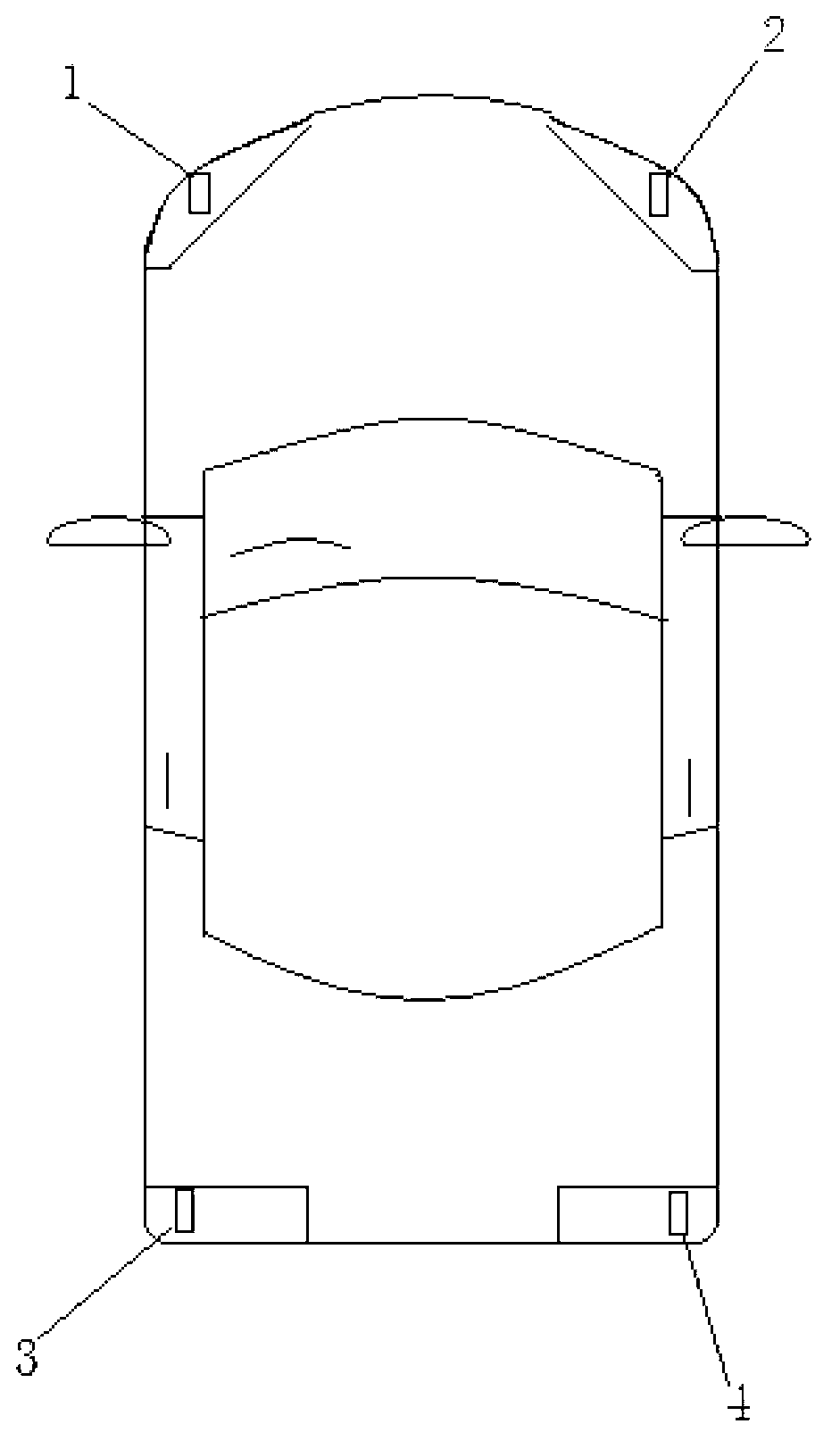
[0019] The layout of the built-in camera device of the vehicle lamp of the present invention is as follows: figure 1 As shown in the figure, the left front camera 1, the right front camera 2, the left rear camera 3, and the right rear camera 4. The four vehicle cameras are respectively packaged in the transparent lampshades of the left headlight, right headlight, left rear taillight, and right rear taillight of the vehicle.

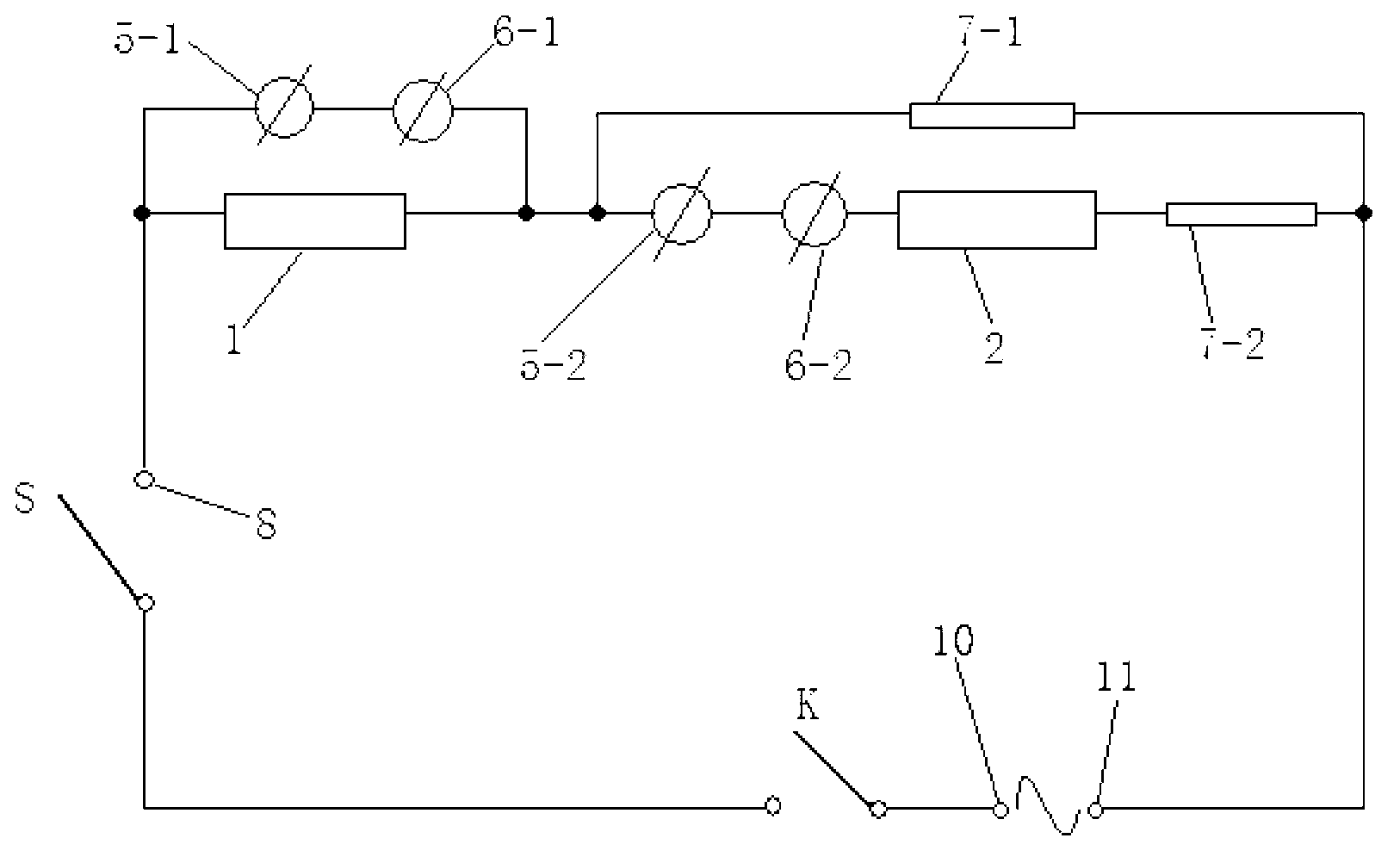
[0020] The control circuit when the car lamp built-in camera device of the present invention is engaged in the forward gear is as follows: figure 2 As shown in the figure, the first vehicle speed range sensor 6-1 and the first direction deflection angle sensor 5-1 are connected in parallel with the left front camera 1 after being connected in series to form a first parallel group; one end of the parallel group is connec...


PUM


Abstract

The invention discloses a built-in camera device for an automobile lamp, which mainly comprises four automobile cameras, namely, a left front camera, a right front camera, a left rear camera and a right rear camera. The four automobile cameras are respectively packaged in transparent lampshades of a left headlamp, a right headlamp, a left rear lamp and a right rear lamp of the automobile. The built-in camera device for the automobile lamp has the advantages: the four automobile cameras are respectively built in the transparent lampshades of two headlamps and two rear lamps of the automobile, so that the requirement for the expansion of the visual field of a driver is met while the cameras are kept clean, the cameras are prevented from being stained by rainwater and muddy water and from being scratched, and a headlamp cleaning device of the automobile is utilized to directly clean the lampshades so as to ensure the cleanness of the cameras. The visualization problem of an angle with the maximal turning radius at the front end of the automobile along the moving direction during the process of pointing the direction in a low-speed and large-angle form is solved.

Description

technical field [0001] The invention relates to a camera device, in particular to a camera device built into a vehicle lamp. Background technique [0002] The driving and reversing video imaging device is a device that is often equipped on high-end cars at present, but the camera is placed outside the headlights: some cameras are installed in the middle of the front grille of the vehicle, and the camera is easily exposed to the outside. The muddy water is dirty, resulting in poor imaging effect; some are only equipped with a reversing camera and the reversing camera is installed above the license plate in the center of the rear of the car, so that it can only take care of the scene directly in front of the rear of the car. End-to-end perspective expansion doesn't help. At present, low-end and mid-range vehicles are rarely equipped with front-facing cameras, and low-end and mid-range vehicles account for the majority in daily road driving. In countries where traffic rules ar...

Claims


Application Information

Patent Timeline
28 Nov 2012
Publication
CN102795167A
IPC
B60R11/04
Inventors
李超