Supporting structure of elevator guide rail

A supporting structure and elevator track technology, applied in elevators, transportation and packaging, etc., can solve problems such as cost increase, achieve the effects of reducing track costs, ensuring bending strength, and reducing bending deformation

Inactive Publication Date: 2012-11-28
MITSUBISHI ELECTRIC CORP
View PDF4 Cites 7 Cited by
  • Summary
  • Abstract
  • Description
  • Claims
  • Application Information

AI Technical Summary

Problems solved by technology

In order to suppress the bending deformation of the bracket caused by this bending moment, it is necessary to take measures to strengthen the bending rigidity by increasing the plate thickness of the conventional bracket, which is a major cause of cost increase.

Method used


Image

  • Supporting structure of elevator guide rail
  • Supporting structure of elevator guide rail
  • Supporting structure of elevator guide rail

Examples


Embodiment approach 1

[0038] Next, Embodiment 1 will be described with reference to the drawings.

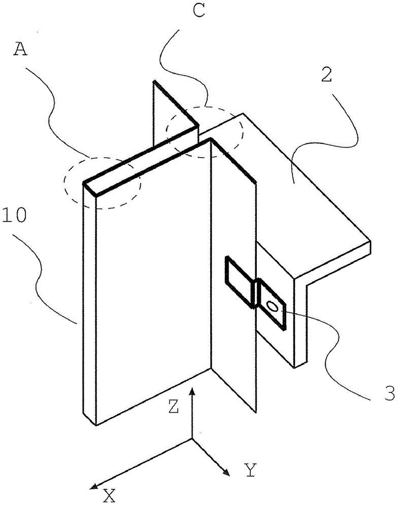
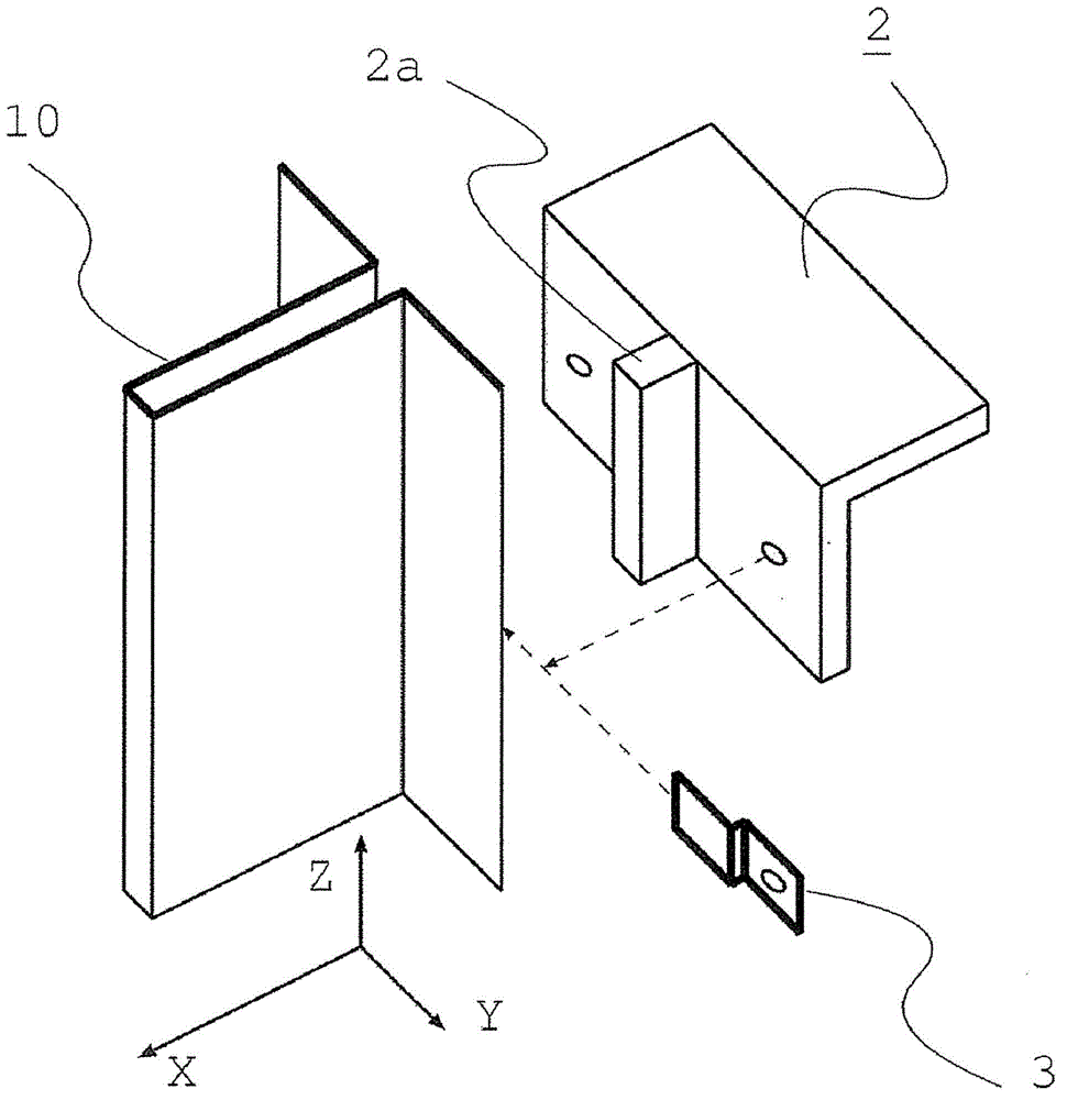
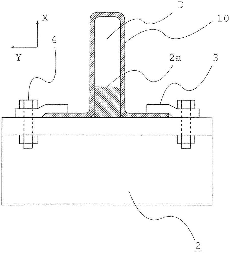
[0039] figure 1 It is explanatory drawing which shows the rail support structure of Embodiment 1 of this invention, figure 2 is the expanded view of the track support structure, image 3 It is viewed from below (the negative direction of the Z axis) figure 1 Horizontal graph of . in addition, Figure 13 , Figure 14 It is a diagram shown for comparison with the present invention, and is a perspective view of a conventional rail support structure and a horizontal plane internal view viewed from the negative direction of the Z axis.

[0040] Regarding the conventional rail support structure, firstly, the Figure 13 Be explained. The car and the counterweight (not shown) travel up and down along the left and right rails 1 respectively. The rail 1 is supported by the bracket 2 via beams (not shown) provided on the building side. A plurality of brackets 2 are arranged vertically at predetermined...

Embodiment approach 2

[0050] Next, Embodiment 2 will be described with reference to the drawings.

[0051] Figure 4 An example of the rail support structure of Embodiment 2 is shown. In the figure, the shape of the steel plate forming track 10 is the same as figure 1 Differently, it is formed into a shape in which a surface folded back in the X-axis direction of the steel plate forming rail is added to the rail flange end (the outer peripheral end portion opposite to the shape center portion of the rail flange portion) (hereinafter, the folded surface The part is called the reentry part). Rail clamp 3 in figure 1 Set in the YZ plane, in contrast, in Figure 4 Set in the XZ plane.

[0052] Next, use Figure 5 The structure of the bracket 2 will be described. The bracket 2 is composed of a pair of channel-shaped members, which are Figure 17 The steel plate shown is bent into a channel shape. The said turn-back part provided at the rail flange end of the steel plate forming rail 10 and the ...

Embodiment approach 3

[0056] Next, Embodiment 3 will be described with reference to the drawings.

[0057] Figure 7 The rail support structure of this embodiment is shown. The shape and Figure 4 Differently, the turning part turns back 90 degrees at the rail flange end to the opposite side of the rail head (part G indicated by the oblique line in the figure). Rail clamp 3 with Figure 4 Also set in the XZ plane.

[0058] Next, use Figure 8 The structure of the bracket 2 will be described. and Figure 5 Similarly, the bracket 2 is composed of a pair of groove-shaped members, and the folded portion provided at the flange end of the steel plate forming rail 10 is in surface contact with the bottom surface of the groove of the bracket 2 .

[0059] also, Figure 9 Indicates details of fastened parts. The rail pressing plate 3 is fastened to the groove bottom of the bracket 2 by bolts 4 , and the folded portion of the flange end of the steel plate forming rail 10 is fixed by the rail pressing...


PUM


Abstract

The invention provides a supporting structure of an elevator guide rail. In the prior art, if the up-down interval of a carrier becomes longer, the horizontal load of an elevator car and a counterweight, when an earthquake happens, may result in the bending of the guide rail, and then the bending strength cannot be ensured. Therefore, if a guide rail having a larger cross section is required, the problem of higher cost of the guide rail arises. The supporting structure of the elevator guide rail includes a steel plate forming guide rail provided with a U-shaped forming part, and a carrier supporting the steel plate forming guide rail, wherein one face of the steel plate forming guide rail and one face of the carrier are defined in that the surfaces of the faces are contacted with each other in the plane determined by the head direction of the steel plate forming guide rail and the axial direction of the steel plate forming guide rail.

Description

technical field [0001] The present invention relates to a rail of an elevator, in particular to a supporting structure of a steel plate formed rail formed by bending a steel plate. Background technique [0002] In conventional elevators, the car and the counterweight are supported by guide rails provided in the hoistway. The guide rail is fixed in the hoistway by a bracket and a rail pressing plate arranged on the building side. If the fixed intervals fixed by the rail clamping plate become longer in the vertical direction, the rail will be greatly deflected under the horizontal load of the car and the counterweight due to the earthquake, and the bending strength of the rail may not be ensured. Therefore, in order to improve the bending rigidity of the track, it is necessary to use a track with a larger cross-sectional area to increase the cross-sectional moment of inertia of the track compared with the previous fixed-space track that lengthens the track in the vertical dir...

Claims


Application Information

Patent Timeline
Patent Type & Authority Applications(China)
IPC IPC(8): B66B7/02
Inventor 渡边诚治宫川健
Owner MITSUBISHI ELECTRIC CORP
Why Eureka
Try Eureka